Grapple Design Ideas

   / Grapple Design Ideas #1  

WhiteRock

Silver Member
Joined
Dec 26, 2004
Messages
210
Location
Central TX
Tractor
Kubota M9000HDC3, Kubota B7500
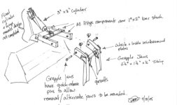
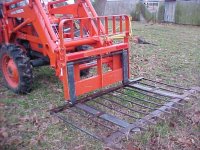
I am designing a grapple/rake bucket for my tractor (Kubota M9000, FEL LA1251A). The doesn't matter, but it will give folks an idea where my thoughts are coming from. Yes, I could buy one, but I wanted to design and build one.

I started this thread for design discussion (in the event any folks are interested) and to not hijack other project progress discussions

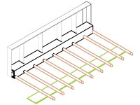
I am currently working on the rake/bucket portion and doing the grapple arm and hydraulics design in my spare time (near 0).

I am not as skilled as the TBN'er here so I have to design and draw. But I enjoy that. I am drawing in a way that I can post on the web. I do not have the skill to totally engineer a grapple, but you never know what one can learn here. I might before it is over.

I have done some work on the geometry of the grapple arm and cylinder pivot locations. I wrote a simple spread sheet to allows me to plug in placement values and it will compute my cylinder stroke. If there is interest I can try to post what I have.

Additions I intend to add to the spread sheet are:
- specify open close angle, have it compute stroke
- specify cylinder diameter and psi, have it compute closing/open force
- other associated grapple design info

Currently I would like to dig up some mechanical physics concepts and compute the pinching force of the grapple while being pushed by a cylinder at an angle.

If this stuff is already out there, maybe I just need pointers.

I will stop here to see if there is any interest in this sort of thing. I just thought it might generate some interesing ideas and reference material for build-it-yourself grapple folks.
 
   / Grapple Design Ideas #2  
WhiteRock -

Reading your post and the other recent grapple post got me thinking "lever calculator"...one google search later - first hit:
Engineers Edge There are 4 different lever calculators - if you go searching through the site there are also hydraulic calculators, and info on types of weld joints! What a great site!

I have been toying around with the idea of a "compound lever" system to change the lever relationship between cylinder stroke and grapple jaw opening (angle) - but nothing firm yet. I am somewhat familiar with this concept because the plastic processing equipment I work with has (toggle-) lever mechanisms.

I'm planning on making some scale "2D" lever models using cardboard cutouts and varying the hinge point distances to get a feel for the required cylinder stroke - or better said: cylinder / hinge placement to get the necessary grapple jaw opening angle. I'd be interested in any lever calculations you had worked out to help with my first draft.

As far as hydraulics go - I simply have a beefy 3" bore / 6" stroke hydraulic cylinder already purchased - if I can use the "big side" of the piston for making the closing force (at the expense of *speed* - which isn't an issue for me) - I don't think I'll have anything to worry about - other than to make sure the grapple can endure pressing against the stops! /forums/images/graemlins/grin.gif But then I think the hydraulic / force calculations are fairly easy.... /forums/images/graemlins/wink.gif

Hoping to get started cutting steel (have some 1 1/2" x 3" x 1/4" rectangular tube that I'm thinking of for the grapple "fingers" - I also have some HEAVY 2" x 1" flat stock - I'm thinking of making the hinge assembly out of the heavier flat stock - and then make two sets of "fingers" that could be removed simply by pulling a pin - the rectangular tubing slides almost perfectly onto the flat stock!

I'd like one heavier set of grapple fingers for lifting rocks, logs and brush - and another set with sort of a coarse mesh / screen (3" x 3" grid") that I could use to sift rocks and other debris from soil and compost.

Looking forward to seeing what everyone is brewing up! /forums/images/graemlins/grin.gif

Dan
 
   / Grapple Design Ideas
  • Thread Starter
#3  
Good stuff already. /forums/images/graemlins/cool.gif

That is a big cylinder. For the 7610, I believe your hydraulics are about 2,000 psi max. That would give you around 14,000 lbs of force. The actual pinching force will be much less with the levers in the closed position. I plan to add this math to my spreadsheet.

I would recommend your design allow you cylinder to fully extend and contract. I think this is better for your implement.

Even with a 3" cylinder, I would be surprised if you have any speed problems. I know some folks have had to add restrictors to slow the operation down. I think they may be using smaller cylinders though. There is another idea. It should be easy to add the open and close times to the spreadsheet as well.

I don't know how much pinching power a grapple should have. I have seen some hold pretty heavy stuff hanging out the bottom of the grapple (WR Long I think).

I have thought about the compound lever as well. It would be neat if a design would allow the grapple to fold into the bucket out of the way, or ...
 
   / Grapple Design Ideas
  • Thread Starter
#4  
I did a little more work on the spreadsheet tonight. I am including the following picture in the spreadsheet in an attempt to make it more usable. I am not a great spreadsheet writer.

I am setting it up to allow entry of distances by letter to letter (A-B, B-C, etc.) and various information will be calculated.

None of this math is particularly complicated, but hopefully this sheet will collect a lot of the math necessary for various hydraulic projects. It is causing me some thinking cramps to set the formulas up to work in anyplace someone wants to put a component.

Currently computing:
- cylinder push and pull force, oil capacity, extension and retraction speed
- cylinder length and stroke to open and close grapple
- grapple pivot placement
- cylinder pivot placement

Work in progress:
- Expanding angles that the grapple can open and close
- grapple load pinching force
- grapple bucket pinching force
- grapple pinching force at specified angle

627900-image002.gif


Anything else I should compute?
 

Attachments

  • 627900-image002.gif
    627900-image002.gif
    4.8 KB · Views: 981
   / Grapple Design Ideas #5  
Whiterock,

Seems like most of the forces are going to change as the jaw position changes. Are you going to calculate those as a function of opening distance and possibly plot them?

The maximum open dimension may be more useful than the maximum open angle.

You may want to confirm that @ max opening, the movable jaw can still touch the ground for back dragging when you uncurl the loader.

Its interesting to see how different TBN people approach the same problem. One guy will do it this way (my tendency) while the next guy will build it, tack it, try it, relocate it...

John
 
   / Grapple Design Ideas
  • Thread Starter
#6  
Yes the forces will change with the jaw position. I had planned to allow the entry of position and show the force. It would be easy to display a table of positions. Its not to difficult to plot as well. I am just worried about making the sheet to complex. I am a low level system programmer and not good with GUI's. Good idea though, I will try to add it. I think folks might be surprised at how these forces change.

I can also add the maximum open dimension. Another good idea.

Confirming the grapple will touch the ground is an interesting one. I will be asking for user input for the vertical dimension of C-E and maybe horizontal dimension of C-E (picture above). Since I expect the user to design the frame, it can be put at the location of choice. I will just help with cylinder choice and forces. This may be all backward...??

It is interesting to see the different approaches. I was amazed with my initial spreadsheet as to how easy it was to manipulate the positions and avoid a big wart on the top of your grapple. This is why I wanted to share it. With all the different ways to do it, it may be more work that I can do. But I am going to give it a try. I will learn something....
 
   / Grapple Design Ideas #7  
WhiteRock -

KubotaBillys pics in the other thread helped me clarify the general location of the hydraulic cylinder mounting - I took a look at my FEL this morning and I don't see any clearance issues (I had originally thought of mounting "behind" the bucket to protect cylinder - way too complex / low on clearance).

I made a quick sketch (attached) of what I have in mind:

- 1" x 2" bar stock will be used for the "hinge" mechanism that the cylinder mounts to, and to in turn - create the jaw opening / closing movements.

- 1 1/2" x 2 1/2" x 1/4" rectangular tubing will be use to fabricate the "jaws" of the grapple. Reinforcement plates / gussetts will likely also be 1/4".

The basic concept is that the hinge mechanism will have two male posts (1" x 2" bar) that will slide into a female receiver (1 1/2" x 2 1/2" tube) on the grapple jaw itself. The grapple jaws and posts will be cross-drilled to allow for a quick-release fixing pin attachment - so that the jaws can quickly be removed - or more importantly - alternate jaw configurations - could be attached.

Initially, I plan a simple, "two-claw" grapple - to be used for moving some brush piles, logs, and mid-sized rock landscaping placement.

I took some pics this morning also - I'll post them later today while at work - but the fit between the bar stock and the tubing is nearly perfect! /forums/images/graemlins/laugh.gif

Hope that helps....

Dan
 

Attachments

  • 628871-DR_Grapple Design 1.0 (600 x 356).jpg
    628871-DR_Grapple Design 1.0 (600 x 356).jpg
    37.8 KB · Views: 937
   / Grapple Design Ideas
  • Thread Starter
#8  
DanR67, nice drawing! That sure is a quick way to convey you ideas.

Here are some alerts to me that I would like to here your thinking on:
- I think a 3" cylinder is way to big for a B7610
- Your high cylinder mount is worrisome and problematic, I think
- Think grapple weight.

I have a B7500, so I think I understand what you are working with. I don't have the hydraulic relief valve pressure here, so maybe I can get it when I get home.

I think a 3" cylinder will "beer can crunch" you bucket and equipment. If you don't already have your cylinder, I would look at something like a 1" cylinder that is short. I will be lighter, easier to work with, and probably pinch all you can pickup. It is good for over a 1,000# extension force.

If you already have the cylinder and must use it, I would consider an adjustable relief valve in the circuit.

The high cylinder mount will increase your exposure to cyl damage. If you are interested, I can propose some placement numbers that will keep the cylinder close. Then you can build a cover over it for protection. This will prevent damage in the event you are ever tempted to close the grapple and push into a pile.

I am not sure, but you may be over designed on strength. We don't have to fly, but excessive weight will tax your implement performance. If the cyl size is reduced, you don't have to worry as much. I had rather bend my grapple that my bucket. I know I tend to design around the materials I have.

I think you will need some kind of reinforcement bar on the top of your bucket.

Good stuff, I will try to think some more about this. Your ideas may work just fine. This is just some of my input for what it is worth.
 
   / Grapple Design Ideas #9  
WhiteRock -

I understand where you are coming from and am in agreement with regards to the 3" cylinder - it is definitely "overkill" for grapple needs.

Having said that - I purchased it last fall along with another 3" x 6" cylinder. The 3" x 6" ended up working out better for me as my 3PH Tilt Cylinder - I thought the 8" stroke would have gone there.... I was just trying to get the shortest - but beefiest - cylinders.

So....yeah this cylinder really is overkill - I was thinking about adding a pressure relief / limiting valve also to keep the forces in check. At full pressure - I would worry about A) tearing the hinge assembly off the back of the bucket or B) "beer can crushing" the bucket as you put it. One way I intended to prevent that would be to have the piston bottom in the cylinder before the claws if the grapple touch the front edge of the bucket...just by playing aroung with the lever geometry.

As I said in my last post - my first grapple is for brush, log and rock moving. The rock moving is what I'll probably get the most use out of - at least initially: brush moving (hopefully) is a once or twice / year affair.

Having moved the "raw steel" around this morning - and throwing in the weight of the hydraulic cylinder - I'd guess that the entire grapple mechanism will add @ 125 lbs to the FEL weight - not an issue for brush and most logs - and I think I should be OK with all but the largest rocks.

Specific to rock moving - I don't think I need that much "force" to hold a rock in the bucket / grapple - I just need enough force to "hold it in place."

I know what you mean about the cylinder mount - Kubotabillys' solution is nice from an open / close geometry standpoint - but the forces that get generated will be *interesting* to tame. That's why I made the note in the sketch I attached: cylinder mount design not completed! /forums/images/graemlins/grin.gif

Finally - I've attached a pic showing the nice fit between the 1"x 2" bar stock and the 1 1/2" x 2 1/2" tube stock - plus a pin for reference. I'm thinking 8-10" of engagement between the two pieces should provide the necessary support to prevent the "claw-tubes" from folding (assuming of course, that I get my big cylinder force under control! /forums/images/graemlins/wink.gif )

I'm still chewing on ideas....but having someone else going through the same exercises is definitely a help! /forums/images/graemlins/cool.gif

Dan
 

Attachments

  • 629045-DSCN1132 (525 x 394).jpg
    629045-DSCN1132 (525 x 394).jpg
    91.4 KB · Views: 772
   / Grapple Design Ideas
  • Thread Starter
#10  
DanR67,
That does fit nice. I like that. I think that will work out well for you. You may find all sorts of things you can do with that attachment.

I like your toplink too. I have never noticed a bar being used like that on the tractor side. Neat.

A little clarification on the crushing issue. I think the design should be done such that the cylinder bottoms just as the arms snugs up tight. This still will not prevent the item you pick up (non-compressible like a log) from crushing your implement. So, IMHO you must have strength to use the tractor's relief valve or add a lower pressure one on the cylinder.

I wonder if you could use a 4 x 3 piece of angle iron attached to the top of the bucket's folded lip. Put the 4" inside the bucket. Put your grapple pivots on the 3" vertical side. Build your rear cylinder support on a plate that bolts on the back of the bucket and through to the angle iron along the top. If the 3" cyl strength is controlled, that should be strong enough and give a very low profile. The next time I am by the B, I'll have to look and see if I think this will work. This is all probably as clear as mud. /forums/images/graemlins/confused.gif /forums/images/graemlins/smile.gif

BTW: I think 125# is a reasonable weight.

Another note, you get better open/close geometry with closely mounted pivots. When you spread them apart, it limits how much you can open. Not good in my opinion.

Good stuff, hope you don't mind my opinions...
 
   / Grapple Design Ideas #11  
</font><font color="blue" class="small">( DanR67,
That does fit nice. I like that. I think that will work out well for you. You may find all sorts of things you can do with that attachment. )</font>

Funny thing is - I got the two pieces of steel from two different scrap yards several weeks apart - can't really ask for more! /forums/images/graemlins/laugh.gif (Well, OK - the steel did have to spend the winter outside under a tarp - so I've got to clean everything up with a wire wheel...Kubotabilly looks like he was working with "freshly minted" steel!)

</font><font color="blue" class="small">( I like your toplink too. I have never noticed a bar being used like that on the tractor side. Neat. )</font>

This was a bit of a necessity - as the original, thread-adjust toplink fit into a bracket - the hydraulic cylinder came with a clevis (?) / fork attachment at each end. SO...I basically had to come up with a "gender-changer" to adapt the cylinder - here a detailed picture. The original toplink rod was attached at the bottom pin IIRC.

</font><font color="blue" class="small">( A little clarification on the crushing issue. I think the design should be done such that the cylinder bottoms just as the arms snugs up tight. This still will not prevent the item you pick up (non-compressible like a log) from crushing your implement. So, IMHO you must have strength to use the tractor's relief valve or add a lower pressure one on the cylinder. )</font>

Yep - I understand this as well. Having the piston bottom is purely to prevent the grapple from crunching when doing an "air grab". The cylinder mount, bucket reinforcement, pivot points / final leverage / moments, and pressure limiting valves all must be designed / matched to the task at hand. I do want to try to make this "idiot proof" so I don't hose something because I stayed on the valve just a bit too long... /forums/images/graemlins/blush.gif


</font><font color="blue" class="small">( I wonder if you could use a 4 x 3 piece of angle iron attached to the top of the bucket's folded lip. Put the 4" inside the bucket. Put your grapple pivots on the 3" vertical side. Build your rear cylinder support on a plate that bolts on the back of the bucket and through to the angle iron along the top. If the 3" cyl strength is controlled, that should be strong enough and give a very low profile. The next time I am by the B, I'll have to look and see if I think this will work. This is all probably as clear as mud. /forums/images/graemlins/confused.gif /forums/images/graemlins/smile.gif

BTW: I think 125# is a reasonable weight.)</font>

I had to re-read this several times - but I get your drift. I like the idea of mounting the grapple pivots to the angle iron - that way the bucket stays nearly untouched - save for some mounting holes. I had also thought of doing some general kind of "bolt through" cylinder mount / reinforcement plate - your idea is just more specific - thanks! /forums/images/graemlins/smile.gif

Re: 125 lb weight: that's my guess-ti-mate. Now thinking about the angle iron and bolt-through reinforcing plates - the whole assembly may go up as high as 150 lbs. Still within reason, I feel.

Long term - one of the options that I have in mind is to build some kind of "quick-attach" system for my FEL bucket - so I could add some front forks in addition to my 3PH forks - don't want to fiddle with bolt-ons, because I think the weight will be too far forward. I plan to move small pallet loads of wood pellets in the front as well as the back - halving my trips. Each pallet weighs: 17 bags x 40 lbs = 680 lbs + the "mini-pallet" (pallets cut in half on the short axis). They are delivered one ton / full pallet (50 bags) - which I cannot move with my B7610 - so I restack them onto 3 "minis" - takes @ 10 - 12 minutes / ton.

If I get around to this - then I would "clean sheet" the grapple - as I would not have the crushing concerns nor geometry / clearance concerns of the FEL bucket to contend with. This would likely also negate the "weight penalty" - as any "pure grapple" would likely weigh less than the FEL bucket.

</font><font color="blue" class="small">( Another note, you get better open/close geometry with closely mounted pivots. When you spread them apart, it limits how much you can open. Not good in my opinion.)</font>

This is the ONE thing my larger cylinder works in my favor for: with the higher forces it can produce - I can place the pivot points closer together and get more "swing" (grapple jaw opening) distance - while producing the same amount of grapple force as a smaller cylinder.

</font><font color="blue" class="small">( Good stuff, hope you don't mind my opinions... )</font>

Thanks - am enjoying your input - as well as seeing / reading the many talents of our fellow TBNers only helps crystalize my ideas. Keep the feedback coming!

Cheers,

Dan
 
   / Grapple Design Ideas
  • Thread Starter
#12  
Here is rough draft drawing of my grapple fork design. I have made several design changes that aren't reflected here. In this drawing, I didn't cut the plate off on the forks in the CAD program.

The square pipe holding the tines is a 6" X 6" X 1/2" X 87". I plan to use 14 tines 42" long, 1.5" diameter, solid. The back plate is not updated and has been changed somewhat.

I am a little concerned about the strength of the 1.5" tines. To avoid bending, I plan to use a 8" X 1/4" plate along the bottom of the tines. I thought I would sharpen this plate so I could push it along the ground and shear small bushes etc. as I get brush.

I am <font color="blue">looking for input </font> on how far back I should place the plate? Anyone have any opinions? I want the tines to be effective, but I don't want to put the plate far enough back to make them weak. I was thinking about 8" from the tip.

631309-Grapple4.jpg
 

Attachments

  • 631309-Grapple4.jpg
    631309-Grapple4.jpg
    84.3 KB · Views: 461
   / Grapple Design Ideas #13  
Take a look at what these guys are building jack bucket I don't see it now, but he was talking about a rotator plate so you could turn the thing upside down or sideways for demolition work to "skim" ceilings or walls. Coupled with a grapple, it is a heckuva design for demoing anything inside or outside.. If you have some time to kill (like an hour or two) call the office @ 218-692-5535 Ask for Del.

Instead of sharpening one edge, maybe you could use a bucket cutting edge?
 
   / Grapple Design Ideas
  • Thread Starter
#14  
This is quite an implement. That one is a lot larger and heavier duty than what I am trying to build. I thought my weight was going to be high! /forums/images/graemlins/grin.gif I just have a lot of clearing to do on my place. So I plan to just be piling a lot of trees for burning.

I thought about using a blade edge, but the shearing function is secondary. I just thought it wouldn't take much to configure during the construction phase.
 
   / Grapple Design Ideas
  • Thread Starter
#15  
Grapple users....

Can you tell me if you always use your grapple arms? Do you really need to hold the load on, or can you pull it out with the rake, then pick it up and carry it away?

I had assumed that the arms need to open to a full vertical position. Do you find this to be the case?

Thanks.
 
   / Grapple Design Ideas
  • Thread Starter
#16  
I am starting to think about the hydraulics for my grapple. I am thinking about adding a selector valve ( I think it is also being called a diverter valve) to my bucket curl circuit like PineRidge has.

Can anyone tell me if the buck shifts under load while activating the grapple selector valve?

The reason I ask is that in reading the specs, it looks like the new circuit starts to open as the other side starts to close. Looks like there would be crossflow causing a pressure release. Is this the case, how does this work?

<font color="blue">Answered: I found the answer to my own question in a previous forum " Electric Hydraulic Valve Kit From W.R. Long - ??? "</font>
 
   / Grapple Design Ideas #17  
This is on my M6800. I like it a lot, but unlike I imagined, I can't just drive along and the branches jump up onto the thing. It slips over some forks I made.

I recomend the slip over the forks concept. It has been very good. Two steel clips hold it on so it won't slip off. I want to make install / remove tool less.
 

Attachments

  • 632916-KOLIBA FORKS DIAGONAL.jpg
    632916-KOLIBA FORKS DIAGONAL.jpg
    70.3 KB · Views: 492
   / Grapple Design Ideas #18  
That's a pretty slick idea. The clips go around the back side of the forks? More details maybe? Thanks
 
   / Grapple Design Ideas
  • Thread Starter
#19  
That's pretty neat. Looks like a nice addition to your forks.

I had thought about making some flexible options for my grapple, but I have decided to make it a dedicated unit. My tines will be about 5" apart which give me 14 tines. To make the tines stronger, I plan to weld the bottom plate to effectively tie them together. Further, I plan to weld small angle iron supports from the tines to the plate.

I also got some addtitional ideas by plowing through some of the older forums as well. One was to make the grapple drop through the tines about 4". This way I can back drag brush with the rake flat.

So I have decided to put the plate back about 8" from the end of the tines. As the grapple come down through the tines, I will have it stop on the plate at the end of the cylinder travel. This will cause the grapple force to push back on all the tines instead of down on them.

My current ideas......
 
   / Grapple Design Ideas #20  
Hi all -

Just to keep ideas flowing: while I'm not prepared to make up a table / calculation for various geometries of grapple cylinders - I do realize - based on Kubotabillys' grapple project - that some planning is in order - mostly because *real estate* for mounting the hydraulic cylinder is at a premium . My problem stems from the cylindrical "cross tube" that connects the FEL arms.

To that end - I though first of making some "scale drawings" / lever models - but when I considered that I would eventually have to recalculate everything....I decided it is much easier to model at 1:1 / full size.

So....here's pic #1 - tracing bucket outline
 

Attachments

  • 633785-Template_Marking.jpg
    633785-Template_Marking.jpg
    74.5 KB · Views: 439

Tractor & Equipment Auctions

2011 MAGNUM PRODUCTS LIGHT PLANT/TANK TRAILER (A58214)
2011 MAGNUM...
207278 (A52708)
207278 (A52708)
CAT 289D3 (A58214)
CAT 289D3 (A58214)
2019 KOMATSU D61PXI-24 CRAWLER DOZER (A60429)
2019 KOMATSU...
2012 INTERNATIONAL 4300 26 FT BOX TRUCK (A59904)
2012 INTERNATIONAL...
60'' SKID STEER BUCKET (A56857)
60'' SKID STEER...
 
Top