You are using an out of date browser. It may not display this or other websites correctly.
You should upgrade or use an alternative browser.
You should upgrade or use an alternative browser.
Grapple Design Ideas
- Thread starter WhiteRock
- Start date
- Views: 19440
More options
Who Replied?
/ Grapple Design Ideas
#21
DanR67
Silver Member
DanR67
Silver Member

DanR67
Silver Member
DanR67
Silver Member
DanR67
Silver Member
That looks like a good way to get a good feel for your spacing. If that is you cylinder, looks like you should have plenty of room. You cylinder shouldn't be that far down behind your bucket should it?
Have you looked at this design ?
You could also do something simliar to this, and just modify the cylinder mounting.
I think based on your pictures, the angle iron mount will also work.
Looks like in pic 7, you are trying to put your cylinder to far back to me....
What are you cylinder's dimensions?
DanR67
Silver Member
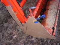
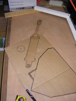
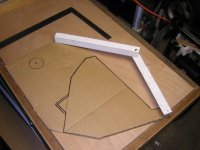
Pic #8 - Last one.
This one shows a template that I made over the winter to work out the best "angle" that I will make the grapple "claws" at. This is before I came up with the cardboard template idea - but same principle - the two pieces of wood are hinged with a 1/4" carriage bolt.
*****************
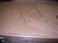
So the next step is to experiment with layouts. I am mulling over the basic design of the toggle / lever system that will convert the linear motion of the hydraulic cylinder into the rotational motion of the grapple jaw opening / closing. As Whiterock pointed out - I'm concerned about mainly two points:
1) force transmission / strain on bucket (due to size of 3" bore cylinder - pressure reduction valve is a viable work-around)
2) location of cylinder to minimize potential damage
I plan on simply driving in finish nails / screws at the hinge points of the lever templates and observe general grapple opening / closing "movements" & clearances - especially with regard to the cylinder / cross tube.
I guess I forgot to note: I made the template with the bucket fully *curled* - so the cross tube - grapple cylinder should only be critical at that time.
************
I thought that might help kick start some other folks' ideas - and it's a lot easier to cut cardboard than steel! (although I'd debate that cutting steel is likely more fun... /forums/images/graemlins/grin.gif )
Hope that helps,
Dan
This one shows a template that I made over the winter to work out the best "angle" that I will make the grapple "claws" at. This is before I came up with the cardboard template idea - but same principle - the two pieces of wood are hinged with a 1/4" carriage bolt.
*****************
So the next step is to experiment with layouts. I am mulling over the basic design of the toggle / lever system that will convert the linear motion of the hydraulic cylinder into the rotational motion of the grapple jaw opening / closing. As Whiterock pointed out - I'm concerned about mainly two points:
1) force transmission / strain on bucket (due to size of 3" bore cylinder - pressure reduction valve is a viable work-around)
2) location of cylinder to minimize potential damage
I plan on simply driving in finish nails / screws at the hinge points of the lever templates and observe general grapple opening / closing "movements" & clearances - especially with regard to the cylinder / cross tube.
I guess I forgot to note: I made the template with the bucket fully *curled* - so the cross tube - grapple cylinder should only be critical at that time.
************
I thought that might help kick start some other folks' ideas - and it's a lot easier to cut cardboard than steel! (although I'd debate that cutting steel is likely more fun... /forums/images/graemlins/grin.gif )
Hope that helps,
Dan
Attachments
DanR67
Silver Member
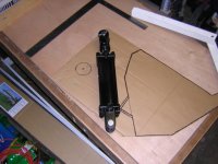
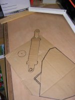
WhiteRock -
I have seen the grapple design from ATI - but when I look at their cylinder - if looks fairly compact - even apparently with a fairly decent piston stroke.
I think this design would be tough with the cylinder I have because of it's overall length - IIRC it's @ 19" fully closed - so thats @ 27" with the full 8" stroke extended. I'm not saying it isn't possble - I just have to play around with the layout...My only other concern: the long "support tube" and flanges that bolt to the sides of the bucket must add considerable weight to the design.
Because of the cylinder size (ie 3" bore) and potenttial force it could produce - I was thinking of mounting the cylinder to a "subframe" - a one piece carrier that would absorb all the cylinder force at one end directly - and then perhaps act on a lever at the other end - so that most of the force is not transmitted directly to the bucket...perhaps a bit tough to explain...but also still just a thought. (The "subframe" could be as simple as a deep piece of C-Channel stock that the cylinder could "nest in" for added protection as well.
I'm hoping I'll simply have an "Eureka!" moment while I'm staring at my pile of steel - but I defintiely wanted to mess around with some different "mechanisms" before I got to cutting steel. Thought this would help someone as well...
Dan
PineRidge
Super Member
It won't work. As soon as it rains the cardboard will get mushy and you'll loose your load. /forums/images/graemlins/wink.gif
Sometimes it's best to just jump in there and start working with the steel.
As long as you just tack weld things together you can still make changes as you go.
And of course there are LOTS of folks here willing to help you if a surprise jumps up.
Go for it............
Sometimes it's best to just jump in there and start working with the steel.
As long as you just tack weld things together you can still make changes as you go.
And of course there are LOTS of folks here willing to help you if a surprise jumps up.
Go for it............
That right! Just think, if cutting and tacking it together is fun, you may actually enjoy making a mistake! After you grind and cut it apart, you can weld pieces back together before you restart!
I never thought it could be this much fun! Screw this drawing and paper doll stuff! /forums/images/graemlins/grin.gif /forums/images/graemlins/cool.gif /forums/images/graemlins/grin.gif
I never thought it could be this much fun! Screw this drawing and paper doll stuff! /forums/images/graemlins/grin.gif /forums/images/graemlins/cool.gif /forums/images/graemlins/grin.gif
DanR67
Silver Member
</font><font color="blue" class="small">( It won't work. As soon as it rains the cardboard will get mushy and you'll loose your load. /forums/images/graemlins/wink.gif )</font>
LOL! /forums/images/graemlins/grin.gif
But seriously - I know what you mean about "just do it" with steel - and for sure I plan on improvising "on the fly" when construction actually begins. Much of this also has to do with the materials I have on hand - I have a (very) general idea of what I think this will look like - but I may see a piece of angle iron that "fits" part of the puzzle - but only after having completed some of the assembly...
This happened when I was designing my 3PH fork frame - I started off with one thing in mind - then "bingo" - I saw how I could assemble things differently (and in this case - fewer cuts) - and the whole design crystalized in a matter if minutes! /forums/images/graemlins/cool.gif
But of course...I'll be here beggin' for advice here when (not if!) I've screwed something up.... /forums/images/graemlins/blush.gif /forums/images/graemlins/grin.gif
Dan
I really think you should consider making a design assumption to limit the 3" cylinder force. Remember you always want to break the grapple before your bucket or loader frame.
If you analyze KubotaBilly's design (of course his FEL was a lot stronger) it is quite interesting how it works. He also used some pretty strong steel. But in the last few degrees before closure, his force on the buck is down to a few hundred pounds, the rest is trying to pull the steel bar apart. This way there are no damaging forces on the loader. As the loader open it gets stronger quick with the max strength at full open.
I you don't you this technique, consider a relief valve.
Well.... Did you take PineRidge's advice? Are you cutting steel?
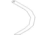
I seem to have hit a hay bale... I am having trouble with my grapple arms. I drew the attached grapple arm in CAD and sent it out for a quote. I specified 1/2" X 28" X 32" with a 1" hole. It came in at $306 per arm. So that's not going to work. I could almost buy a grapple for that. I am a little spoiled I guess, I have been paying $0.15/lb for my steel. But this is a complex cut. I sure need that plasma cutter.
Actually at the above price, I could buy my plasma cutter, and do it myself and have the machine left over.
I am starting to think about a way to weld a bunch of angle iron together to make my arms. It wouldn't be pretty. I don't mind the welding. I just have to make it strong enough. I am just not sure what to do at the moment.
I still have some calls into folks for quotes to see what they come up with. I may try PineRidge's man, Andy I believe.
Attachments
notamustang
Gold Member
WhiteRock 1/2" is pretty thick, what I was thinking on mine is to use a skill saw with many abrasive blades. Of course I was looking at 5/16 for mine. Mine will have little to no rock use though. Maybe a ROP program at a high school, you could supply them with that 15 cents a pound steel and have them cut it.
<font color="blue">1/2" is pretty thick </font>
I agree. My grapple is pretty big though and I am going to move some big and long stuff. I have no idea whether 1/2" is necessary or not. I have looked at some other heavy duty grapples and they use 1/2". I probably could get by with 3/8" and make sure I get gussets in the right places.
If I were smarter about the correct strength, I could keep my weight down and improve my grapple performance. I guess that is what you get with amateur built. It will still be a lot of fun and a lot of satisfaction from building it myself.
notamustang
Gold Member
<font color="blue"> It will still be a lot of fun and a lot of satisfaction from building it myself.
</font>
Oh no doubt about that /forums/images/graemlins/grin.gif /forums/images/graemlins/grin.gif /forums/images/graemlins/grin.gif
<font color="blue"> If I were smarter about the correct strength, I could keep my weight down and improve my grapple performance.</font>
<font color="red"> You and me both!!!! </font> /forums/images/graemlins/grin.gif /forums/images/graemlins/grin.gif /forums/images/graemlins/grin.gif
On my BX with a tooth bar I am thinking of adding a flow reducer to the dump function because of the noticable added weight giving a really quick dump. I need to save weight were ever I can on my lil toy /forums/images/graemlins/grin.gif
DanR67
Silver Member
</font><font color="blue" class="small">( Well.... Did you take PineRidge's advice? Are you cutting steel? )</font>
WR -
No - I wish, though. Still doing some "honey-do" projects - the power for my welder is in an out-building - so unless I'm up for a *shocking* experience - I won't be welding outside unless the weather is OK....which means "honey-do" tasks at the moment... /forums/images/graemlins/frown.gif
Having said that - I swung by my local metal recycler last Saturday and picked up some additional stock - some 1/4" and 3/8" plate stock that looks like it should work nicely for reinforcements / gussets etc. I have also brought all the intended steel stock into the garage - so at least I can cut some pieces if the "mood" strikes me.... /forums/images/graemlins/cool.gif
**************
BTW - the 1/2" for your jaws sounds like the right thickness - but hoo! that's pricey! Although it won't give you the nice edge - what about oxy-acetylene cutting them? I can't imagine using a jig- / sabre-saw to cut 1/2" plate - those will take quite a while and use LOTS of blades....
I like the idea of buying your plate - and then contacting a local trade school to do the plasma cutting - I'd bet that would be much more reasonable!
Slow going here too... /forums/images/graemlins/frown.gif
Dan
I have another question....
I want to put bushings on my grapple arm pivots. Any ideas on how to make these? I was planning to use 1" pins. It looks like one could use 1" schedule 80 pipe and drill it to one 1".
I noticed that Kubotabilly said he used schedule 40. I think that has a wall of .133. Is that to thin for me? I have been looking for schedule 80 which I think has a .179 wall. Is that thick enough?
Any ideas on a source for Schedule 80? or other material to make them?
I checked a hardware store that claimed they sold all their schedule 80 black pipe (gas pipe I think) that day. I will try to check back with them, but it sounded like an item they didn't sell a lot of.
jmc
Elite Member
- Joined
- Jul 21, 2003
- Messages
- 3,221
- Location
- SW Indiana
- Tractor
- Ford 1920 4x4 (traded in on Kubota). Case 480F TLB w/4 in 1 bucket, 4x4. Gehl CTL60 tracked loader, Kubota L4330 GST
Whiterock,
Sch 40 1 inch has a ID of 1.049. After you true up the ID it might be a little sloppy for a 1 inch shaft, especially if you want to put a grease zerk in it.
Sch 80 1 inch ID is .957 and about perfect to clean up for a nice fit with a 1 inch shaft. If you're welding it, distortion may require that you drill or bore it after welding, unless you make the ID enough oversize to handle the distortion.
I found 1 inch schedule 80 in the local pipe distributor's cutoff box. They still charged 2 or $3/ft.
John