Help Interpreting Wiring Diagram & Using Multimeter

   / Help Interpreting Wiring Diagram & Using Multimeter
  • Thread Starter
#51  
what I'm trying to do... which is write a resume, in preparation for an upcoming job interview/test on Tuesday.
Add a few beers in the mix and golly does my mind wander...

dieselcrawler, WOW, Been There Done That many a time........The difficulty, taking each and every skill mix you have, both (HR Type) Personnel Interaction i.e., individual contributor or Heavy Team Player + Formal or Technical Education, practical skills, then, recognizing the Company's Specialties and the Job Posting, create a hit list and address each and every theme or technical area in paragraph form down the line. The Bullet lists resumes are for speed readers but having meat (verifiable facts) will make the difference. I use to do a search on the Company and find people's resumes that were either working in the area or previously, LinkedIn profiles to also helped ...Wish you well.............

Yes, the mind does wonder but Margaritas (multiples) + Jalapeno & Cheese Nachos (extra hot) burns right thru that, just be sure you partake a couple days in advance before any Interviews, etc., due to the after effects it might present........OUCH :fiery:
 
   / Help Interpreting Wiring Diagram & Using Multimeter
  • Thread Starter
#52  
For a while there it looked like the pull winding was bad. Now am i correct that he is going to have to make his voltage measurements under load as the issue looks like the issue is up stream of the solenoid? If that is the case i would start with the easy stuff and supply a ground directly from the battery to the solenoid . If memory serves me correct pull in draws more amps, so bad ground could show up on pull-in side and not hold in. So, checking ground first, will get 50% out of the way.

truckdiagnostics, THANKS for the Response.

Like you I too thought the pull winding was bad, no such luck so yes, I'll have to get the Wiring Diagram in-hand and start following voltage upstream :reading:...... Interesting "Bad Ground" concept, as someone not skilled in this space I'll work thru this and for years to come other people not so skilled like me, they will be able to take small steps to achieve a bigger goal, get the tractor moving again.......:)
 
   / Help Interpreting Wiring Diagram & Using Multimeter #53  
In a nut shell the same test you made unplugged you now have to make with the solenoid plugged in and actuated. The hardest part will be figuring out how to back probe the plug. Sometimes you can get a paper clip to follow the wire, go under the seal and touch the pin. There is a plastic coating on paper clips just make sure to clean that off if going the route. Keep track of battery voltage when you make your tests.
 
   / Help Interpreting Wiring Diagram & Using Multimeter #54  
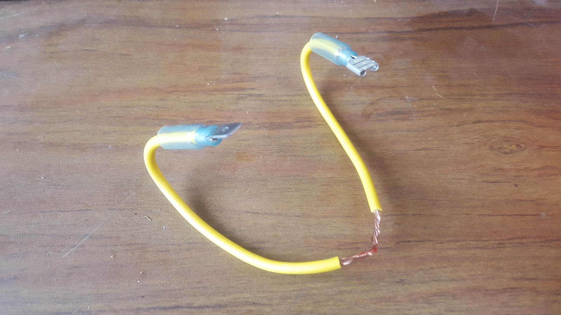
A nice little box of electrical connectors to make a jumper between the tractor harness connector and the solinoid connector, would allow easy access to each wire without damage to the connectors. I'll try to post a picture of what I'm talking about sometime tomorrow.
 
   / Help Interpreting Wiring Diagram & Using Multimeter #55  
Egon, I remembered you saying you had (2) FS and to be sure it wasn't bad before a purchase. What did yours finally turn-out to be.

That is still a question to be answered! If there is thermistor I can't find it. I finally found three things that may work. Jump start. Heat gun on solenoid and pump priming lever. Choice words and random slap on the cowling.

Then one day the clack is back for no known reason??? The clack dissapears the same way.

On mine it requires about Half an hour to get the solenoid out and to get at the conector. Next time it's out the conector will get changed and moved.
 
   / Help Interpreting Wiring Diagram & Using Multimeter
  • Thread Starter
#56  
A nice little box of electrical connectors to make a jumper between the tractor harness connector and the solinoid connector, would allow easy access to each wire without damage to the connectors. I'll try to post a picture of what I'm talking about sometime tomorrow.

truckdiagnostics, dieselcrawler Good Morning, finally some rain here, albeit slight..........:raincloud:

truckdiagnostics, I see my use of the term "coil" was improper when referring to the Pull-In and Hold-In mechanical properties or "Windings" as you appropriately called them. One test I did not perform which I'll head out to do, From Battery to Solenoid Connector's White & Black Wires (only) for Pull-In Function. It's beyond me that the 12 volts coming thru the Harness (as measured) to the Pull-In didn't retract the Plunger but direct power simultaneously to both the Pull-In and Hold-In did.

Not understanding the properties of the Windings, :scratchchin: can there be bleed over so-to-speak from one circuit to another, Pull-In vs. Hold-In and that extra voltage in combination provided the needed voltage for a worn (if they even wear down) Pull-In winding.....As you can tell I'm talking out of school on this.....

So, if I apply direct voltage just to the Pull-In circuit and it works then not not enough juice (technical term) voltage coming from the "J" Junction of the A1 Time Delay Control Module or maybe connections faulty..... Looking at the K2 Fuel Relay, I wouldn't think that would affect the 12v going to the # 651 Wht/Blu to the Solenoid's Wht Wire.....

dieselcrawler - It will be interesting to see your lash-up jumper cables, I will certainly look at the voltage readings under load, especially the mystery "Pull-In" measurements.

NOTE TO SELF: All Birdfeeders in at night, (1) smashed and (2) of (3) MIA this morning :bear:
We do carry Jimmy-Jumbo Belt Holster Pepper Sprayers while venturing in the woods........
 
   / Help Interpreting Wiring Diagram & Using Multimeter
  • Thread Starter
#57  
One test I did not perform which I'll head out to do, From Battery to Solenoid Connector's White & Black Wires (only) for Pull-In Function....

I see in my last post (above) I was in error, I meant to write RED & Black Wires, White Wire is for "Hold-In".

Tested the solenoid "Red Wire" (Pull-In) three times to ensure the voltage connections from the battery A-OK. Nothing, NOT-TA, no retraction. Perhaps that only works when voltage is simultaneously applied to the Hold-In Winding......:scratchchin:
 
   / Help Interpreting Wiring Diagram & Using Multimeter #58  
dieselcrawler,

I was wondering if the Voltage Level could be the case, the Solenoid really came to life with the straight/unfiltered shot of 12v simultaneously to the PULL-IN & HOLD-IN Coils..... Wonder if the 10-12 Volt readings to the Y2 Fuel Shutoff Solenoid #X5 Connector was really lower or maybe the Pull-IN Voltage is too short a duration coming in from the A1 Time Delay Control Module.....

It didn't make any sense getting those in-range voltage readings @ X5 Connector then reconnecting the Solenoid and not enough to pull in the Plunger but just enough to hold it in when manually depressed & especially now that we know the solenoid does retract under 12v. I'll restart my testing all over again tomorrow since I have it apart and report back later in the day, maybe Zebrafive will chime-in with some thoughts.
Time to enjoy the rest of the weekend............ Thanks again for your Technical Guidance, far cheaper for me to spend the time checking this before giving-in and the JD Shop Meter starts running...........

Did you bench test each wire separately?
I see you had good results when testing simultaneously.
If you bench test just 12v to white wire any pull in? If not, it may require 12v to both wires for pull in the 12v only to the red wire for hold in.
I am guessing a separate test to the red wire has not results. (pull in needed from the white wire first?)
Are you able to test; first to white and then ADD 12v to red, THEN drop 12v from white? What happens?

I agree you can get "good" meter readings, but still not work. You need both voltage AND current. Meter was only measuring voltage.
I think I would start with the ground. Bad grounds cause a lot of headaches. On the harness side of the connector, can you access the black wire? Untape to get to it? I would strip some insulation off the black ground wire. Splice on another wire (at least the same gauge) (wrap on and solder would be the best) then run this wire to the battery ground terminal, or same bolt battery ground wire connects to frame/engine.

If a "better ground" does not help, I would look for loose/corroded connections for the red and white wires.

I doubt the relay is the problem, but you could swap with another relay on the tractor. It may have burnt contacts inside that are creating a voltage drop.
 
   / Help Interpreting Wiring Diagram & Using Multimeter
  • Thread Starter
#59  
Did you bench test each wire separately?
I see you had good results when testing simultaneously.
If you bench test just 12v to white wire any pull in? If not, it may require 12v to both wires for pull in the 12v only to the red wire for hold in.
I am guessing a separate test to the red wire has not results. (pull in needed from the white wire first?)
Are you able to test; first to white and then ADD 12v to red, THEN drop 12v from white? What happens?

I agree you can get "good" meter readings, but still not work. You need both voltage AND current. Meter was only measuring voltage.
I think I would start with the ground. Bad grounds cause a lot of headaches. On the harness side of the connector, can you access the black wire? Untape to get to it? I would strip some insulation off the black ground wire. Splice on another wire (at least the same gauge) (wrap on and solder would be the best) then run this wire to the battery ground terminal, or same bolt battery ground wire connects to frame/engine.

If a "better ground" does not help, I would look for loose/corroded connections for the red and white wires.

I doubt the relay is the problem, but you could swap with another relay on the tractor. It may have burnt contacts inside that are creating a voltage drop.

Zebrafive, Thanks for the post............

dieselcrawler is going to show me his jumper set-up to do for further testing. I'm using some wiring I had laying around but hard getting it to stay rigid within the connector, something like alegator clips if easily inserted into the connectors would be much easier. Per your previous post:

The fuel shut off solenoid colors red, white, black are:
Red = Pull in coil
White = Hold in coil
Black = Ground


This morning I did a separate Bench Test on the solenoid Red/Black "Pull-In" Winding, NOT-TA, No Retraction of the Plunger.
 
   / Help Interpreting Wiring Diagram & Using Multimeter #60  
Jumpers shown, x3, easy to make up, and allows testing and/or Jumpers while things are hooked up properly. Any auto parts store or hardware store would have the crimp on ends shown, take your solinoid with you to get the right size blade male/female ends.


Install jumpers between factory connectors, make double sure you keep them going to the matching positions.
 

Tractor & Equipment Auctions

2003 Big Tex 10PI 16ft. T/A Pipe Top Utility Trailer (A49461)
2003 Big Tex 10PI...
5ft Disc Harrow (A48837)
5ft Disc Harrow...
International 574 Tractor (A50860)
International 574...
2019 KENWORTH T680 TANDEM AXLE SLEEPER (A50505)
2019 KENWORTH T680...
Brouwer Hitch-Hiker 3600-R Piggyback Forklift (A49346)
Brouwer...
2021 John Deere Z997R Diesel Zero Turn Mower (A50490)
2021 John Deere...
 
Top