Here I go again

   / Here I go again #11  
Those figures seem high for this reason. Charge pumps usually pump about 10% of the main pumps capacity. If you calculate the HP required to run that pump, you would come out with a 30 GPM pump, would require 62 HP, and a 50 GPM pump would require 103 HP . Other than make up oil, it does help keep the tram pump cool.

When you are not mowing, do you connect the hyd lines together? Do you remember the cost of that high pressure filter and was it rated at 10 microns.
The charge pump is a relatively low pressure pump--a couple of hundred psi as I recall--so it doesn't require much power to move 3-5 gallons per minute.

As to the PTO filter it is mounted on the mower on the return side of the mower so it only is used when the mower is used. I did use a high pressure filter becaue of the restriction on the return line at the quick attach fitting on the PT. I purchased the filter at Surplus Center and my recollection of the price is about $200. I posted about it at the time I did the mod and if you search you can find the specific model and cost of the filter. I have a 10 micron filter in it.

Edit: the original post was in this thread: Motor Oil as the Hydraulic Oil in Power Trac
 
Last edited:
   / Here I go again #12  
The tram pump is a closed circuit, that changes everything. I assumed that once the oil circulated through the wheel motors it went back to the reservoir. With a closed circuit I would think the heat buildup would be horrible. Like you said, once debris is in the closed circuit it is in there for good. So if I have this correct, the only oil filtered is make up oil going to the tram circuit, unless I have a leak nothing gets filtered. Strange!!!

I believe that the tram circuit is semi-closed with (as discussed by others) a 3 to 5 gallon makeup. The return to the reservoir goes through the oil cooler, at least according to my schematic. The inlet of the tram pump makeup goes through the filter. So there is cleaning and cooling of the tram circuit. No leak is required for oil to flow in and out of the tram circuit. This is according to the Wheel Motor Circuit drawing dated 8/3/98 that I got with my machine.
 
   / Here I go again
  • Thread Starter
#13  
I believe that the tram circuit is semi-closed with (as discussed by others) a 3 to 5 gallon makeup. The return to the reservoir goes through the oil cooler, at least according to my schematic. The inlet of the tram pump makeup goes through the filter. So there is cleaning and cooling of the tram circuit. No leak is required for oil to flow in and out of the tram circuit. This is according to the Wheel Motor Circuit drawing dated 8/3/98 that I got with my machine.

At least you have a schematic, I have nothing. Would it be possible for you to scan the schematic and post it for the less fortunate, like me?
 
   / Here I go again #14  
Hey swamp, stinks that your having these troubles. Did you get an owners manual when you bought it? Mine came with 7 pages of schematics. My wheel circuit page is dated 7/20/04.

Kris
 
   / Here I go again
  • Thread Starter
#15  
Yes I was given a booklet of part pictures, but no schematics were included.
 
   / Here I go again
  • Thread Starter
#16  
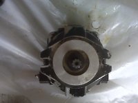
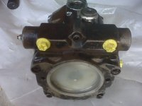
I would love to educate myself on this pump but I don't know the brand or model. From these picture can anyone here identify at least the brand so that I can begin the search?
 

Attachments

  • IMG00012.jpg
    IMG00012.jpg
    68.5 KB · Views: 214
  • IMG00013.jpg
    IMG00013.jpg
    74.2 KB · Views: 207
  • IMG00014.jpg
    IMG00014.jpg
    60.9 KB · Views: 190
  • IMG00015.jpg
    IMG00015.jpg
    67.2 KB · Views: 206
Last edited:
   / Here I go again #17  
I dont remember the final result but I do believe someone identified the brand with the same "omega" symbol ....not sure if they could narrow it down to the same pump though..
Kris
 
   / Here I go again #18  
I believe that the tram circuit is semi-closed with (as discussed by others) a 3 to 5 gallon makeup. The return to the reservoir goes through the oil cooler, at least according to my schematic. The inlet of the tram pump makeup goes through the filter. So there is cleaning and cooling of the tram circuit. No leak is required for oil to flow in and out of the tram circuit. This is according to the Wheel Motor Circuit drawing dated 8/3/98 that I got with my machine.

Maybe this article will make it more clear.

Because the pump and motor leak internally, allowing fluid to escape from the loop and drain back to the reservoir, a fixed-displacement pump called a charge pump is used to ensure that the loop remains full of fluid during normal operation.

In practice, the charge pump not only keeps the loop full of fluid, it pressurizes the loop to pressures between 110 and 360 PSI, depending on the transmission manufacturer. A simple charge pressure circuit comprised of the charge pump, a relief valve and two check valves, through which the charge pump can replenish the transmission loop (Figure 3). Once the loop is charged to the pressure setting of the relief valve, the flow from the charge pump passes over the relief valve and back to the reservoir.

Apart from losses through internal leakage, which are made up by the charge pump, the same fluid circulates continuously between transmission pump and motor. This means if the transmission is heavily loaded, the fluid circulating in this loop can overheat. To ensure the fluid in the transmission loop is exchanged with that in the reservoir and subsequently cooled, a flushing valve is installed in the circuit.

When the hydrostatic transmission is in neutral, the flushing valve has no function and charge pressure is maintained by the charge relief valve, usually located in the transmission pump. When the transmission is operated in either forward or reverse, the flushing valve operates so that charge pressure in the low-pressure side of the loop is maintained by the purge relief valve incorporated in the flushing valve. This purge relief valve is set approximately 30 PSI lower than the charge pump relief valve.

The effect of this is that cool, conditioned fluid drawn from the reservoir by the charge pump, charges the low-pressure side of the loop through a check valve located close to the transmission pump inlet. The volume of hot fluid leaving the motor outlet, which is not required to maintain charge pressure in the low-pressure side of the loop, vents across the flushing valve purge relief and back to the reservoir.

The hydraulic system used on our PT's, are Closed Loop, even though the reservoir is not sealed. The fluid travels through the tram pump through the motors and back to the input of the tram pump. Any other fluid not needed by the closed system, is probably dumped into pump drain and then to reservoir. Some of our wheel motors have motor case drains, and they either combine and go through the tram pump or go through the cooler to the reservoir. There seems to be a flusher type valve on some pumps that relieve the oil from the pump case to cooler to reservoir.

If your tram pump can pump , say 8 GPM, that is 480 GPH at max speed, and the smaller machines only have a 10 gal tank. whereas the larger units have 20 gal tank/reservoir. the oil will heat up quite rapidly. They say to keep the oil below 180 degrees

I think if anybody really wants to know, just put a flow meter in the cooler circuit and you will have an idea of the amount of oil that is being filtered.
 
   / Here I go again #20  
The Omega brand was identified as Bondioli & Pavesi.
 

Tractor & Equipment Auctions

2014 GOOSENECK DRIVER SIMULATOR TRAILER (A45046)
2014 GOOSENECK...
New Holland 611 Backhoe Attachment (A47809)
New Holland 611...
2012 GMC Acadia SUV (A46684)
2012 GMC Acadia...
2024 BCL Fabrication Landscape Dump Trailer - Heavy-Duty Utility Trailer for Mulch Debris Hauling (A46884)
2024 BCL...
International Hay Dryer (A47809)
International Hay...
2012 Chevrolet Malibu Sedan (A46684)
2012 Chevrolet...
 
Top