hydraulic cylinder (trig-angle calculations)

   / hydraulic cylinder (trig-angle calculations) #21  
Your cyl acts along a continuously varying vector that is the hypotenuse. It is the force. We are going backward here and are resolving that force into 2 constituent parts at right anges to each other. Same exact idea looking at it from a different perspective.
larry

Nice explanation!:D:D
 
   / hydraulic cylinder (trig-angle calculations) #22  
Next thing you know the stress and strain of this conversation is going to cause someone to make it Mohr than it has to be.
 
   / hydraulic cylinder (trig-angle calculations) #23  
LD1,

So far, this analysis will probably result in a cylinder larger than you need.
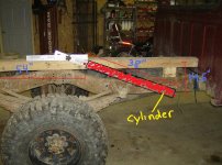
To calculate this more accurately, you need to approach it from the standpoint of torque rather than simple forces. Torque takes into consideration the locations of the pivot point, various centers of gravity, location of the two cylinder attachment points, and load behind the pivot point, if any. For example, that horizontal force component of your cylinder in which no one was really interested in actually works in your favor if the cylinder base is attached below* the pivot point. The torque approach also considers the weight supported by the pivot point which does not need to be lifted by the cylinder. The calculation is simple and amounts to the fact that the sum of all clockwise torques about the pivot must exceed the sum of all counterclockwise torques. Looking at your trailer from the left side, the weight of the trailer bed in front of the pivot causes a CCW torque and the weight of the trailer behind the pivot causes a CW torque. Their respective torques are their respective weights times the HORIZONTAL distances of the centers of gravity from the pivot. Similiarly for payloads in front and behind the pivot. The vertical component of the cylinder times the horizontal distance between its attachment to the bed and the pivot point is a CW torque. So is the horizontal cylinder force component times its base attachment point distance below the pivot. Try different cylinder sizes at max pressure and find one where the CW torque is greater than the CCW torque.

*Vertically below but not necessarily directly below


Quarencia,

That's bad! You'll have Mr. Mohr circling in his grave.

John
 
   / hydraulic cylinder (trig-angle calculations)
  • Thread Starter
#24  
I appreciate all the responses so far.

I just want to be clear:
I understand the correct formula and will size my cylinder according to its numbers.

I don't want to re-invent the wheel here, I just want to get a better understanding of it and why it works out the way it does instead of the force vector method that I explained. I know it somehow works out to be correct but I just don't quite understand how yet.
 
   / hydraulic cylinder (trig-angle calculations) #25  
Try different cylinder sizes at max pressure and find one where the CW torque is greater than the CCW torque.

I think you are right.

OTOH, the only harm from an oversized cylinder is to the finances. Undersize the cylinder and overload the truck and you will discover this fact when it won't raise up. This is going to be a mighty PITA. Especially since opening the gate and unloading whatever you were intending to dump first removes the material which contributes least to the torque requirement for raising the box.
 
   / hydraulic cylinder (trig-angle calculations) #26  
LD1,
I plugged your geometry into the spreadsheet I made to design my grapples. (A cylinder with 30" of travel and a 34" retracted length? That's compact!)
I use pin-pin distances and the law of cosines to calculate angles, then use the sum of torques. I get a theoretical max load of 9567lb centered 51" in front of the pivot. I think your original calculations were correct where you calculated the vertical force vector in post #1 then did a sum of torques in post #15.

I can't seem to make the zipped file work...
 
Last edited:
   / hydraulic cylinder (trig-angle calculations)
  • Thread Starter
#27  
Well I am going to have to change the design a little bit. I got the bed off and there is just no room for a cylinder and crossmember beefy enough between the frame rails. Its got a huge gas tank that would be in the way. So I plan on using two 2.5" x 30 inch cylinders mounted on the outsides of the frame rails.

With the cyl mounted 54" ahead of the rear pivot, 14.5" drop (22.5*) will give me 10,500lbs dump and a 56.8* dump angle.

I have attached some pics. first is the plan. last three are to show the lack of room between framerails
 

Attachments

  • HPIM0743.JPG
    HPIM0743.JPG
    90.5 KB · Views: 1,805
  • HPIM0744.JPG
    HPIM0744.JPG
    156.3 KB · Views: 462
  • HPIM0745.JPG
    HPIM0745.JPG
    131.5 KB · Views: 500
  • HPIM0746.JPG
    HPIM0746.JPG
    130.2 KB · Views: 671
   / hydraulic cylinder (trig-angle calculations) #28  

Attachments

  • zforduplarge.jpg
    zforduplarge.jpg
    198.4 KB · Views: 2,329
   / hydraulic cylinder (trig-angle calculations) #29  
Managed to get Brad_Blazer's file extracted and open. Somehow it was zipped twice. Tried to repost it, but I keep getting the same problem.

So this is what I did to open it. Open zip file and extract the file. This file will have no extension on it. Add ".zip" extension to the file name and open this new zip and extract the excel file.
 
   / hydraulic cylinder (trig-angle calculations) #30  
I think in the end the conclusion is correct.

With a pivoting design, moments determine whether the bed will lift or not. Typically, the maximum load on the hydraulic cylinder occurs right at the point when the bed starts to lift off the frame rails. From there it gets easier and easier since the center of gravity moves closer to the pivot (horizontally) and the load will start being reduced (dumped) before too long.

Since the horizontal component of the thrust acts through the hinge of the bed, it contributes nothing to lift. The vertical component causes an anti clockwise moment. The load (not shown in your sketch), causes a clockwise moment.

The magnitude of the lift moment is 28800*sin(28)*3ft = 40 562 ftlb

The weight that can be lifted with the bed horizontal @ 51" from the pivot is 40 562/(51/12) = 9544lb That includes the weight of the bed of course, so the payload will clearly be less.

I did a spreadsheet to calculate the numbers and it looks like the max bed tilt is about 55 degrees and the maximum lift (in the bed) is 14.5k @ 45 degrees. Not that it matters, since you can only lift 9k from level.
 

Attachments

  • Dump Bed.jpg
    Dump Bed.jpg
    47.8 KB · Views: 3,335
 
Top