hydraulic schematics

   / hydraulic schematics
  • Thread Starter
#11  
<font color="blue"> "Currently, the valve has an inlet port, an outlet port, and 4 work ports (the work ports connect to the cylinders). By removing the plug and inserting the power beyond sleeve, you now have added an additional outlet port. This port is the power beyond port that allows fluid to flow to the next valve." </font>


I have you up to here.


<font color="blue"> "The "old" outlet port is still there and now becomes the return to tank port, and you still have the the inlet port." </font>

Now I'm lost.........

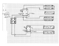
If I use the old "outlet port", where do I get my pressure from? I have reposted an attachment showing my system. Both systems appear to be independent except for the blocks at the tranny.
 

Attachments

  • 824405-3930_hyd_sch.jpg
    824405-3930_hyd_sch.jpg
    80.1 KB · Views: 876
   / hydraulic schematics #12  
Pressure comes when a spool is actuated. Open center systems must have a continuous flow path from pump to tank.

The following explanation assumes the 2 blocks in your system are independent of each other. Based on your diagram I believe they are.

In order to connect the grapple, are you going to use a diverter on the curl cylinder circuit or add an additional directional control valve to control just the grapple?

For now let's assume you want to add an additional control valve. For this case, either the new valve or the existing valve must have power beyond capability. The one you choose to have power beyond will have to be placed in series before the one that doesn't have power beyond.

Let's say you want to add PB to the existing loader valve because the new valve you just bought for the grapple does not have PB. To connect the valves in the circuit, you must first remove the PB plug on the loader valve and replace it with the PB sleeve. The existing outlet connection that returns to tank will stay just as it is, returning to tank. Now, connect the PB outlet from the loader valve to the inlet of the new valve. The outlet of the new valve will connect to the return to tank line of the loader valve since this is the last valve in the circuit (return to tank lines can be teed together).

Since this is an open center system, fluid will flow into the loader valve, out its PB port, into the new valve inlet, and out the new valve and return to tank.

When a loader valve spool is actuated fluid will flow thru a work port, into a cylinder and exhaust fluid from the cylinder will flow back thru a work port and exit thru the return to tank port. Fluid not used by the spool will continue on to the new valve thru the PB outlet.

Adding a diverter to the curl circuit is much easier but may be a little more expensive.
 
   / hydraulic schematics
  • Thread Starter
#13  
I think the light bulb just got a little brighter.....we shall see..

<font color="blue">" The outlet of the new valve will connect to the return to tank line of the loader valve since this is the last valve in the circuit (return to tank lines can be teed together) </font>

So if I understand you correctly, I can just tee in the return port of the grapple's directional control valve into the loaders return to tank line. And if this is the case, could I not just plug the return to tank port on the loaders directional control valve( first in series), and move the tank return line to the grapple's directional control (last in series) valves return port?

That is assuming that all fluid not used by the loader is sent to the grapple control valve through the power beyond circuit and then returned to tank.

Am I getting close?
 
   / hydraulic schematics #14  
hbarski,
I thought you wanted to control the grapple from your existing joy stick.
I also believe that being able to activate the grapple independent of the other functions is the best way to go.

Ron
 
   / hydraulic schematics #15  
Getting close.

</font><font color="blue" class="small">( I can just tee in the return port of the grapple's directional control valve into the loaders return to tank line. And if this is the case, could I not just plug the return to tank port on the loaders directional control valve( first in series), and move the tank return line to the grapple's directional control (last in series) valves return port? )</font>

The loader valve with PB needs to have a separate return to tank line for work port exhaust fluid. If you plug that line then the exhaust fluid from the cylinders will have no where to go.

The return to tank lines can be connected together. They are the only lines in the circuit that can be teed. It doesn't matter how you plumb them as long as the tank line from the PB valve and the outlet line from the new valve (last in circuit) both go directly to tank.
 
   / hydraulic schematics
  • Thread Starter
#16  
ok, then that clears that up.

Now to address the previous post, yes, I would like to control the grapple from the loader joystick. I like the idea of one handed control.

<font color="blue"> I also believe that being able to activate the grapple independent of the other functions is the best way to go. </font>

Am I headed in the wrong direction? Could this not be an electrical directional control valve? How would plumbing in a directional control valve prevent independent functioning of the grapple? (light bulb starting to dim)
 
   / hydraulic schematics #17  
</font><font color="blue" class="small">(
I like the idea of one handed control. Am I headed in the wrong direction? Could this not be an electrical directional control valve? )</font>
Yes, it can be done with a solenoid valve (what you called electrical directional control valve), or a electric diverter.
WR Long sells complete soleniod kits for many tractors, try giving them a call...They may have just what your looking for.
 
   / hydraulic schematics #18  
<font color="blue"> Am I headed in the wrong direction? Could this not be an electrical directional control valve? How would plumbing in a diretional control valve prevent independent functioning of the grapple? (light bulb starting to dim) )</font> </font>

I was refering to the conversation you have been having with Mad in regards to the Prince valve. The picture you showed is a lever style valve.
Yes a directional control valve is the way to go. There are several manufacturers of kits that include the valve and new handle, with a button, for your joystick.

Ron
 
   / hydraulic schematics
  • Thread Starter
#19  
That (2 spool prince vlv) is what I have presently, I wanted to add the solenoid operated directional control valve(DCV) to control the grapple.

Now I am a bit confused about the diverter versus the DCV.

If I understand correctly, and please feel free to correct me if I am off again, the diverter just switches fluid flow from the curl circuit to the grapple circuit.

The diverters operation is still dependent on manual input control from the 2-spool prince valve, (ie: I would press and hold a switch then move the load lever left or right to open and close the grapple.

The solenoid operated DCV would be an independent operation and could be operated simutaniously while lifting or curling. (ie: Toggle the switch to open and close the grapple irregardless of any other loader valve action.)

Unless I am wrong or confused, which is very likely, I would prefer independent operation. What likely scenarios would warrant the diverter in preference to the DCV?
 
   / hydraulic schematics #20  
You are correct in your assumptions. The valve installed in the power beyond circuit would allow the grapple to work independently of the loader controls.

Ron
 

Tractor & Equipment Auctions

2017 KOMATSU PC228USLC-10 EXCAVATOR (A51242)
2017 KOMATSU...
RIDE AND DRIVE INFO (A50774)
RIDE AND DRIVE...
(2) Oliver Wheel Weights (A50515)
(2) Oliver Wheel...
2010 Ford Edge SE SUV (A51694)
2010 Ford Edge SE...
2015 FORD F-250 XL SUPER DUTY TRUCK (A51406)
2015 FORD F-250 XL...
2015 Ford Explorer AWD SUV (A50324)
2015 Ford Explorer...
 
Top