hydraulic schematics

   / hydraulic schematics #1  

hbarski

Bronze Member
Joined
Apr 3, 2005
Messages
69
Location
Tenn/Arkansas
Tractor
3930 Ford/Newholland Mitsubishi MT2001D CASE 580 CK
I know that I am not the sharpest tool in the shed, therefore I am asking for clarification on hydraulics for a grapple. I have tried to search the forums, and have not been able to find the information I am looking for. Hopefully, the forum will continue to provide me with a limitless depth of knowledge.

I have 3930 New Holland with a 7209 FEL that is controlled with a 2-spool prince valve/single joystick. I cannot tell if it is a power beyond valve. It does have a port labeled BYD that is plugged.

The tractor also has rear remotes that control the top -n- tilt cylinders. It is a smaller valve but is like the FEL valve except it has a port that is labeled PB, and it too is plugged.

I am trying to visualize the schematic for what I would need to do in order to add a grapple to the FEL. I am confused about all the talk of diverters, flow multipliers and directional solenoids. Is there a simplier way to visualize these different scenarios?

I would like to be able to control the grapple from the joystick if possible. I have a lot of brush cleanup to do.

Your help would be greatly appreciated.
 
   / hydraulic schematics #2  
hbarski,
<font color="blue"> (I am confused about all the talk of diverters, flow multipliers and directional solenoids. Is there a simplier way to visualize these different scenarios?)

<font color="black"> There are several ways to accomplish what you want to do.
The diverter is a valve that connects to your existing rear hydraulic outlets, I have seen these divided upwards of eight times. When the existing outlet is activated you use a button to select where you want the fluid diverted to. For simplicity sakes think about you garden hose. The hose on your home is your existing rear hydraulic connector. If you want to connect more than one hose to the end you buy one of those "y" valves at the hardware store. This is the diverter. When you turn the hose on (activate your rear SCV) you now have one supply and a choice of two hose outlets.
The directional valve would be used on your power beyond circuit. It is the same concept as the diverter accept the fluid is constantly flowing through the valve. When you activate the valve it directs the flow to the work ports (the other outlets). These can also be set up to divert to many different outlets.
The solenoids in both cases are just the mechanism that activates the valve when you push the button.

Hope this helps. /forums/images/graemlins/cool.gif

Ron
 
   / hydraulic schematics #3  
</font><font color="blue" class="small">( I would like to be able to control the grapple from the joystick if possible </font><font color="blue" class="small">(

The absolute best way to do this is with a electric diverter, it basically takes the curl circuit, and splits it into two different circuits. So the joystick works the same, left and right operation curls/dumps the bucket. When you push a switch on the joystick, the left and right now operates the grapple.
There are kits you can buy, or you can make your own as several of us have done. Expect to pay about $400-500 for this setup. nothing about hydraulics are cheap!
 
   / hydraulic schematics
  • Thread Starter
#4  
OK, so a directional control valve that is plumbed into the power beyond circuit would have continious pressure available, without relying on a secondary input? That is I could operate all three axis ( lift, curl, grapple) at the same time if desired?

This would be more desirable to me. The next question is concerning the power beyond circuits. I am assuming that this is like a pressure manifold? I basically understand aviation hydraulics. Pressure, suction/return, and bypass. If I can relate to that, I would grasp the concepts quicker.( sorry, it's the old polack(dog), new trick thing)

How do I determine if the prince spool valve is capable of power beyond? Are the ports that are labelled [BYD] and [PB] these power beyond circuits (pressure manifolds)?

What, if any additional plug is required there? How do I route return fluid from the grapple cylinder? What about bypass fluid?

Can anyone show me a simplified schematic?
 
   / hydraulic schematics #5  
OK, so a directional control valve that is plumbed into the power beyond circuit would have continious pressure available, without relying on a secondary input? That is I could operate all three axis ( lift, curl, grapple) at the same time if desired?
//

I don't think so unless you have a closed center hydraulic system. Can you raise and dump at the same time now ?
Ben
 
   / hydraulic schematics
  • Thread Starter
#6  
Yes, I can raise/lower, and curl/drop at the same time.

per surpluscenter catalog, and image attached.


2 Spool Joystick
Valve w/Float
ITEM 9-4782
$227.50 • Brand new PRINCE. Two spool joystick valve for operating double acting cylinders. Ideal for use on front end loaders, lift trucks, and other mobile equipment. The two spools can be operated independently or simultaneously
depending on handle movement. First spool float. Open center. Spring centering.
 

Attachments

  • 824251-catalog279.jpg
    824251-catalog279.jpg
    5.8 KB · Views: 527
   / hydraulic schematics #7  
The Prince valve you listed is capable of power beyond functionality. You have to purchase the power beyond sleeve and install it where the plugged port labeled [byd] is. The other outlet port now becomes the return to tank line which is used for exhausted work port fluid. The power beyond port will be used to connect to the inlet of the next valve in the circuit.

If there are no more valves after the joystick valve then power beyond functionality is not needed. It all depends on how the hydraulic circuit(s) on your tractor is/are plumbed. Most tractors have a hydraulic implement circuit that goes from the tank to the pump to the loader valve to the 3pt and back to the tank.
 
   / hydraulic schematics
  • Thread Starter
#8  
I had you close there, but you lost me again.

"The other outlet port now becomes the return to tank line which is used for exhausted work port fluid"

What other outlet port are we talking about? I don't recall seeing any other outlet ports. I have tried to draw the system as it is now. Where do I port the return fluid?
 

Attachments

  • 824330-3930_hyd_sch.jpg
    824330-3930_hyd_sch.jpg
    80.1 KB · Views: 5,131
   / hydraulic schematics #9  
Currently, the valve has an inlet port, an outlet port, and 4 work ports (the work ports connect to the cylinders). By removing the plug and inserting the power beyond sleeve, you now have added an additional outlet port. This port is the power beyond port that allows fluid to flow to the next valve. The "old" outlet port is still there and now becomes the return to tank port, and you still have the the inlet port.
 
   / hydraulic schematics #10  
Power Beyond output goes to input of new valve, Out of new valve T's into the Out of existing valve. New valve doesn't need Power Beyond unless you add a 3rd valve. Work ports go to cylinders.
 
   / hydraulic schematics
  • Thread Starter
#11  
<font color="blue"> "Currently, the valve has an inlet port, an outlet port, and 4 work ports (the work ports connect to the cylinders). By removing the plug and inserting the power beyond sleeve, you now have added an additional outlet port. This port is the power beyond port that allows fluid to flow to the next valve." </font>


I have you up to here.


<font color="blue"> "The "old" outlet port is still there and now becomes the return to tank port, and you still have the the inlet port." </font>

Now I'm lost.........

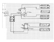
If I use the old "outlet port", where do I get my pressure from? I have reposted an attachment showing my system. Both systems appear to be independent except for the blocks at the tranny.
 

Attachments

  • 824405-3930_hyd_sch.jpg
    824405-3930_hyd_sch.jpg
    80.1 KB · Views: 886
   / hydraulic schematics #12  
Pressure comes when a spool is actuated. Open center systems must have a continuous flow path from pump to tank.

The following explanation assumes the 2 blocks in your system are independent of each other. Based on your diagram I believe they are.

In order to connect the grapple, are you going to use a diverter on the curl cylinder circuit or add an additional directional control valve to control just the grapple?

For now let's assume you want to add an additional control valve. For this case, either the new valve or the existing valve must have power beyond capability. The one you choose to have power beyond will have to be placed in series before the one that doesn't have power beyond.

Let's say you want to add PB to the existing loader valve because the new valve you just bought for the grapple does not have PB. To connect the valves in the circuit, you must first remove the PB plug on the loader valve and replace it with the PB sleeve. The existing outlet connection that returns to tank will stay just as it is, returning to tank. Now, connect the PB outlet from the loader valve to the inlet of the new valve. The outlet of the new valve will connect to the return to tank line of the loader valve since this is the last valve in the circuit (return to tank lines can be teed together).

Since this is an open center system, fluid will flow into the loader valve, out its PB port, into the new valve inlet, and out the new valve and return to tank.

When a loader valve spool is actuated fluid will flow thru a work port, into a cylinder and exhaust fluid from the cylinder will flow back thru a work port and exit thru the return to tank port. Fluid not used by the spool will continue on to the new valve thru the PB outlet.

Adding a diverter to the curl circuit is much easier but may be a little more expensive.
 
   / hydraulic schematics
  • Thread Starter
#13  
I think the light bulb just got a little brighter.....we shall see..

<font color="blue">" The outlet of the new valve will connect to the return to tank line of the loader valve since this is the last valve in the circuit (return to tank lines can be teed together) </font>

So if I understand you correctly, I can just tee in the return port of the grapple's directional control valve into the loaders return to tank line. And if this is the case, could I not just plug the return to tank port on the loaders directional control valve( first in series), and move the tank return line to the grapple's directional control (last in series) valves return port?

That is assuming that all fluid not used by the loader is sent to the grapple control valve through the power beyond circuit and then returned to tank.

Am I getting close?
 
   / hydraulic schematics #14  
hbarski,
I thought you wanted to control the grapple from your existing joy stick.
I also believe that being able to activate the grapple independent of the other functions is the best way to go.

Ron
 
   / hydraulic schematics #15  
Getting close.

</font><font color="blue" class="small">( I can just tee in the return port of the grapple's directional control valve into the loaders return to tank line. And if this is the case, could I not just plug the return to tank port on the loaders directional control valve( first in series), and move the tank return line to the grapple's directional control (last in series) valves return port? )</font>

The loader valve with PB needs to have a separate return to tank line for work port exhaust fluid. If you plug that line then the exhaust fluid from the cylinders will have no where to go.

The return to tank lines can be connected together. They are the only lines in the circuit that can be teed. It doesn't matter how you plumb them as long as the tank line from the PB valve and the outlet line from the new valve (last in circuit) both go directly to tank.
 
   / hydraulic schematics
  • Thread Starter
#16  
ok, then that clears that up.

Now to address the previous post, yes, I would like to control the grapple from the loader joystick. I like the idea of one handed control.

<font color="blue"> I also believe that being able to activate the grapple independent of the other functions is the best way to go. </font>

Am I headed in the wrong direction? Could this not be an electrical directional control valve? How would plumbing in a directional control valve prevent independent functioning of the grapple? (light bulb starting to dim)
 
   / hydraulic schematics #17  
</font><font color="blue" class="small">(
I like the idea of one handed control. Am I headed in the wrong direction? Could this not be an electrical directional control valve? )</font>
Yes, it can be done with a solenoid valve (what you called electrical directional control valve), or a electric diverter.
WR Long sells complete soleniod kits for many tractors, try giving them a call...They may have just what your looking for.
 
   / hydraulic schematics #18  
<font color="blue"> Am I headed in the wrong direction? Could this not be an electrical directional control valve? How would plumbing in a diretional control valve prevent independent functioning of the grapple? (light bulb starting to dim) )</font> </font>

I was refering to the conversation you have been having with Mad in regards to the Prince valve. The picture you showed is a lever style valve.
Yes a directional control valve is the way to go. There are several manufacturers of kits that include the valve and new handle, with a button, for your joystick.

Ron
 
   / hydraulic schematics
  • Thread Starter
#19  
That (2 spool prince vlv) is what I have presently, I wanted to add the solenoid operated directional control valve(DCV) to control the grapple.

Now I am a bit confused about the diverter versus the DCV.

If I understand correctly, and please feel free to correct me if I am off again, the diverter just switches fluid flow from the curl circuit to the grapple circuit.

The diverters operation is still dependent on manual input control from the 2-spool prince valve, (ie: I would press and hold a switch then move the load lever left or right to open and close the grapple.

The solenoid operated DCV would be an independent operation and could be operated simutaniously while lifting or curling. (ie: Toggle the switch to open and close the grapple irregardless of any other loader valve action.)

Unless I am wrong or confused, which is very likely, I would prefer independent operation. What likely scenarios would warrant the diverter in preference to the DCV?
 
   / hydraulic schematics #20  
You are correct in your assumptions. The valve installed in the power beyond circuit would allow the grapple to work independently of the loader controls.

Ron
 

Tractor & Equipment Auctions

UNUSED FUTURE ML32 - 32" MINI HYD MULCHER (A52706)
UNUSED FUTURE ML32...
2016 VERMEER PD10 PILE DRIVER (A60429)
2016 VERMEER PD10...
(INOP) JLG E300AJP ARTICLATED MANLIFT (A60429)
(INOP) JLG E300AJP...
KOMATSU PC490LC-10 EXCAVATOR (A60429)
KOMATSU PC490LC-10...
1979 Ford H-48 Excavator (A56438)
1979 Ford H-48...
John Deere 6195R (A60462)
John Deere 6195R...
 
Top