installing hydraulic thumb

   / installing hydraulic thumb #11  
Just connect the valve to a cyl and test the function.
 
   / installing hydraulic thumb
  • Thread Starter
#12  
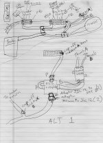
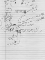
Not sure what I would be testing for hooking up a cylinder. I know the hydraulics are one way, and I will need two way for the thumb. I know the existing solenoid is screwed into a block that has only two hoses attached. I don't follow how specifically I would feed off of it to operate the thumb.
 
   / installing hydraulic thumb #13  
I did not realize you only had one path for the fluid.

Then what you need is a one spool valve to operate the thumb cyl. Feed the spool valve with the solenoid flow.

One other option is to use a SA cyl with a spring to return the thumb to the rest position. Then you could use the solenoid to feed the thumb . Similar to a hyd press.
 
   / installing hydraulic thumb
  • Thread Starter
#14  
Did you see the diagram attached to post #8? The hoses I want to use to lead out to the thumb are teed into the outlet hose and the hose downstream of the solenoid respectively. So when you say feed the spool valve off of the solenoid flow, it is not clear where to attach which hoses. This is my first time working on hydraulics. I try to figure things out by what I can find on the net and in the service manual, but so far the information I have come across does not make it clear how to proceed with the setup I have. If the diagram I posted is not clear as to what I have, perhaps I should post some photos.
 
   / installing hydraulic thumb #15  
How many ports on your solenoid valve.

I am assuming that fluid flows into the solenoid valve and out to the return line until you energise the valve at which time, the flow follows another path.

Is that the one path you want to use.?

In your drawing, it seems you have teed off the pressure line.

You have another acc line that tees into a return line. Is that a line you added

Do you have two acc lines?
 
   / installing hydraulic thumb
  • Thread Starter
#16  
How many ports on your solenoid valve.

---Just 2 large ports.

I am assuming that fluid flows into the solenoid valve and out to the return line until you energise the valve at which time, the flow follows another path.

---That is also what I was guessing after making up the diagram, the other path you refer to, I suppose consists of my two accessory hoses

Is that the one path you want to use.?

---I would use any path but I do need to tap into those accessory hoses somehow, even if it means just disconnecting them and putting plugs where they are teed in. But then I would still need a supply to tap into. I would like to use the following type of valve and not have to tap into any of the existing control valves. I believe that would be easiest with the best outcome. But I have to know how to rearrange the plumbing to hook it up given the existing setup. However, please tell me if you think there is a better way.

12 VDC 10 GPM OC DA SOLENOID VALVE

In your drawing, it seems you have teed off the pressure line.

You have another acc line that tees into a return line. Is that a line you added

Do you have two acc lines?

---I have not added anything. This is the way the machine was when I bought it. No other accessory lines and as far as I know the breaker hydraulics was a factory option. It is these tees and bypasses partly that has me confused in the first place.

thanks
 
   / installing hydraulic thumb #17  
Since you want to control a DA cyl, if you don't need the solenoid, then remove it and add a single spool valve to control the thumb.

The PB or OUT from the BH valve will feed the thumb valve.

Tank line goes to tank.

PB from the thumb valve goes to the 3pt.
 
   / installing hydraulic thumb
  • Thread Starter
#18  
IMG_0580.jpgIMG_0581.jpgIMG_0582.jpgIMG_0583.jpgIMG_0585.jpg
first picture shows backhoe valve stack with accessory hoses in foreground

Second picture shows outlet section in foreground; the smaller teed in pipe is one of the accessory hoses. The larger pipe runs to the solenoid

Third picture shows the other side of stack. The main valve of the stack in foreground. The lower hose leads to the respective lower port of the main valve on the loader stack, which is the main relief valve for the machine.

Fourth picture shows solenoid. The second hose on the solenoid leads to the fifth picture.

In the fifth picture, the hose in foreground is the tee that goes over and ties into the main hose going from the main loader valve to the backhoe stack. Also in this picture, the larger and smaller connections lead to the solenoid and the other accessory hose respectively. What doesn't show up in the photo, is that the pipe also runs back to the tank.

All this is what I was trying to show in the diagram.
 
   / installing hydraulic thumb
  • Thread Starter
#19  
Ok it is starting to make sense, except I'm still not sure what to do with all these teed off hoses. Right now all I need to do is figure out exactly what to buy in the manner of valves, hoses, adaptors and plugs, since the metric adaptors are going to have to be ordered. The thumb itself should be arriving any day.
 
   / installing hydraulic thumb
  • Thread Starter
#20  
Since you want to control a DA cyl, if you don't need the solenoid, then remove it and add a single spool valve to control the thumb.

The PB or OUT from the BH valve will feed the thumb valve.

Tank line goes to tank.

PB from the thumb valve goes to the 3pt.

---What is the 3pt?
thanks
 

Tractor & Equipment Auctions

JOHN DEERE 560M LOT NUMBER 28 (A53084)
JOHN DEERE 560M...
2005 Ford F-350 4x4 Service Truck with Crane, VIN # 1FDWX37P55EB97537 (A51572)
2005 Ford F-350...
2007 Chrysler Pacifica SUV (A51694)
2007 Chrysler...
2010 Ford Edge SE SUV (A51694)
2010 Ford Edge SE...
https://www.accessnewswire.com/newsroom/en/healthcare-and-pharmaceutical/slimjaro-vs-burnjaro-reviews-a-comprehensive-analysis-of-benefits-and-1044755
https://www.accessn...
12 in Large Excavator Bucket (A52377)
12 in Large...
 
Top