wpchrist
New member
- Joined
- Jul 11, 2020
- Messages
- 13
- Tractor
- JD 5420, JD 5425, JD 5075M, JD 310SJ, Hydratrek D2488B
Hello,
I've been visiting this forums for years, but have only recently registered, so first let me say thanks to all the members who have contributed their knowledge and insights over the years.
We have a 2006 John Deere 5425 cab model. Over the years we have used it almost exclusively as a sidecutter (it has a Tiger Mower sidecutter on it). A few weeks ago our 5075 had hydraulic issues that sent it to the shop. That left us without a tractor to pull our CX15 Batwing, so we put the 5425 to work pulling that as well. As a sidecutter, the 5425 was never asked to work very hard...a slow drive to the work location, and a slow drive while sidecutting. The only issue we ever noticed was that the tractor would occasionally not start if left sitting with less than half a tank of fuel. Now that this tractor is pulling an implement and working hard all day other symptoms have appeared. When the tractor gets close to half a tank of fuel it loses power, surges and can't hold itself at 2400 RPMs (or 1500 RPMs in ePTo).
Once this happened I started doing some research and discovered this is an ongoing problem with these tractors. Apparently the fuel tank is a little too low and, without an inline fuel pump, the tractor starves for fuel. One solution is to add a 12v fuel pump as described in John Deere's tech bulletin number 54399. This is the route we decided to take. My local John Deere dealer printed out the tech bulletin for us and ordered the parts listed on the bulletin. When I picked up the parts and read through the bulletin I had several questions. The bulletin is not very clear for implementing this repair. However, I've figured out most of the mechanical questions, but I still am left with the electrical questions.
Here is a photo of the parts. Note some were not on the bulletin parts list, but we ordered them to be pro-active.

Parts List Key:
1. Quick connector
2. Fuel pump
3. Fuel pump clamp
4. Fuel pump mounting plate
5. Small wiring harness
6. Large wiring harness
7. Elbow
8. Barb fitting
9. Barb fitting nut
10. Fuel/water separator*
11. Check valve*
12. Strainer*
13. Bolt
14. Nut
15. Nut, plastic-fits pump electrical terminal
16. Nut- fits pump electrical terminal
17. Tee fitting for fuel return line
18. Quick connector
19. Hose clamps (not shown)
20. O-rings (not shown) for each end of elbow #7
*Not included in tech bulletin parts list
**We also bought new 3/8 bulk fuel line for supply & 1/2" fuel line for return. These are not shown here.
***The elbow (#7 in photo) was filled as part # 38H5015. The bulletin calls for part # 61M5015 which includes the o-ring that goes between the elbow and the barb fitting.
The parts list includes two wiring harnesses. A large harness and a small harness. The small harness connects between the large harness and the fuel pump. The large harness is the confusing one.
Here is the tech bulletin,
*********************************************************************************


************************************************************************************************************************************************
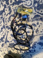
In photo 54399f you can see the upper half of the new fuel pump in the bottom center, Notice the wiring harness with two leads attaching to the pump. This is the small wiring harness called for in the tech bulletin.
Here are my questions:
-How do I access the PTO switch to connect the pump wiring harness to the cab harness (we have a manual PTO)?
-Where is the "accessory junction block" where the red and black leads are supposed to connect?
The instructions say to "run the harness branch with the relay and the 'tee' connectors across the back of the cab and under the cover with the controller."
-What "cover" and which "controller" do I run the harness under?
Further, the instructions say to "remove the RE206064 jumper plug from the main harness and place the 'tee' in between."
-Where do I find this "jumper plug"?
In the last paragraph of the instructions, it reads,
-Does this negate the previous instructions to connect the fuel pump harness between the PTO switch and the cab harness?
-Do I want to splice in to the PTO harness and risk messing that up?
-If I splice into it, where do I find it and which wires do I splice into?
-Which eyelet do I change? and on which harness? The fuel pump harness or the cab harness?
-Is it necessary to have this big harness with a relay and a tee connection to run a single 12 volt fuel pump?
-If I do use the new fuel pump harness, Where does the relay mount?
-Couldn't I just run a power wire from the pump directly to 12v switched power, and a ground from the pump to suitable ground? This would eliminate all the above questions.
I know this is a lot, but any help, especially from someone who has done this install or has experience with wiring these things would be greatly appreciated.
Thanks in advance for any help.
I've been visiting this forums for years, but have only recently registered, so first let me say thanks to all the members who have contributed their knowledge and insights over the years.
We have a 2006 John Deere 5425 cab model. Over the years we have used it almost exclusively as a sidecutter (it has a Tiger Mower sidecutter on it). A few weeks ago our 5075 had hydraulic issues that sent it to the shop. That left us without a tractor to pull our CX15 Batwing, so we put the 5425 to work pulling that as well. As a sidecutter, the 5425 was never asked to work very hard...a slow drive to the work location, and a slow drive while sidecutting. The only issue we ever noticed was that the tractor would occasionally not start if left sitting with less than half a tank of fuel. Now that this tractor is pulling an implement and working hard all day other symptoms have appeared. When the tractor gets close to half a tank of fuel it loses power, surges and can't hold itself at 2400 RPMs (or 1500 RPMs in ePTo).
Once this happened I started doing some research and discovered this is an ongoing problem with these tractors. Apparently the fuel tank is a little too low and, without an inline fuel pump, the tractor starves for fuel. One solution is to add a 12v fuel pump as described in John Deere's tech bulletin number 54399. This is the route we decided to take. My local John Deere dealer printed out the tech bulletin for us and ordered the parts listed on the bulletin. When I picked up the parts and read through the bulletin I had several questions. The bulletin is not very clear for implementing this repair. However, I've figured out most of the mechanical questions, but I still am left with the electrical questions.
Here is a photo of the parts. Note some were not on the bulletin parts list, but we ordered them to be pro-active.
Parts List Key:
1. Quick connector
2. Fuel pump
3. Fuel pump clamp
4. Fuel pump mounting plate
5. Small wiring harness
6. Large wiring harness
7. Elbow
8. Barb fitting
9. Barb fitting nut
10. Fuel/water separator*
11. Check valve*
12. Strainer*
13. Bolt
14. Nut
15. Nut, plastic-fits pump electrical terminal
16. Nut- fits pump electrical terminal
17. Tee fitting for fuel return line
18. Quick connector
19. Hose clamps (not shown)
20. O-rings (not shown) for each end of elbow #7
*Not included in tech bulletin parts list
**We also bought new 3/8 bulk fuel line for supply & 1/2" fuel line for return. These are not shown here.
***The elbow (#7 in photo) was filled as part # 38H5015. The bulletin calls for part # 61M5015 which includes the o-ring that goes between the elbow and the barb fitting.
The parts list includes two wiring harnesses. A large harness and a small harness. The small harness connects between the large harness and the fuel pump. The large harness is the confusing one.
Here is the tech bulletin,
*********************************************************************************
For Cab and IOOS Tractors only.
1. Fuel system loses prime after sitting several days and tractor is hard to start.
2. Engine RPM drops suddenly.
Problem or Situation :
1. The tractor fuel supply allows fuel to drain back towards the fuel tank causing the injection pump to lose prime, resulting in hard starting.
2. While operating under a load, the engine will suddenly lose RPM. The fuel system and injection pump test results are within specification, but the tractor is starving for fuel under certain conditions.
Solution :
Check for any leaks, loose clamps, restrictions, and pinched fuel hoses. Also inspect the fuel strainer, the check valve, and the fuel filter primer assembly's plugs and diaphragm. If these items to not resolve the issue, installing an electric fuel pump may help.
Install electric fuel pump and re-reroute lines.
1. Cut the fuel supply line and install electric fuel pump AL168483. See photos for mounting: 54399a. 54399b.
2. Route the pump outlet to the Filter inlet - 1 piece line.
3. On the Front side of the Filter Head, remove the plug that is on the Engine side. Install 61M5015 Elbow fitting, the opening should be facing downward. Install Barbed Fitting R268896 and Nut 38H5078. See photo: 54399c.
4. Use the same size Fuel line that is used for the Return line.
5. Route the line from this fitting on the Filter Head, to the Rear of the engine where the Fuel Return line connects.
6. Install N154080 Tee Fitting, this Tee will connect the Return from the Engine & Filter/Water Separator to the Fuel Return to Tank line. See photos: 54399d. 54399e.
7. Disconnect the PTO switch, the pump wiring harness will connect between the PTO switch & the cab harness.
8. Connect the red and black wires with ring terminals to switched power at the accessory junction block and the long lead (green and black) to the fuel pump using the short jumper harness. Unless the harness manufacturer made a mistake; the wire terminals on the pump are sized differently to fit the correct terminals. Also, the end of the pump is marked near the terminal posts. See photo: 54399f.
9. Run the harness branch with the relay and the å…¸ee connectors across the back of the cab and under the cover with the controller. See photo: 54399g.
10. Remove the RE206064 jumper plug from the main harness and place the å…¸ee in between.
FOR MACHINES WITH MECHANICAL PTO:
1. For power, splice into the PTO switch harness connection at the mechanical engagement handle.
2. Change the eyelet on the harness to connect to the main fuse panel stud.
3. Run a ground wire to a suitable location on the tractor..
_________________________________________
To install this pump you must order the following parts.
(1) - R269133 - Fuel Pump Mounting Plate
(1) - AL169412 - Clamp
(1) - 19M7867 - Screw
(1) - 14M7298 - Flange Nut
(1) - AL168483 - Fuel Pump
(1) - AL154046 - Fitting
(1) - RE218699 - Fitting
(1) - 14M7139 - Nut
(1) - R270247 - Nut
(1) - RE270815 - Wiring Harness
(1) - RE271703 - Wiring Harness
(1) - 61M5015 - Elbow Fitting (consists of 38H5015 elbow and T77814 o-ring)
(1) - R268896 - Barbed Fitting (this will be added to the end of 61M5015)
(1) - 38H5078 - Nut
(1) - N154080 - Tee Fitting
(4) - RE187161 - Clamp
Additional Information :
Reference electrical schematic R195771 or section SE 1.
IMPORTANT: Installing an electric fuel pump is not feasible for Straddle Mount or Narrow Tractors. Instead, check for any leaks, loose clamps, restrictions, and pinched fuel hoses. Also inspect the fuel strainer, the check valve, and the fuel filter primer assembly's plugs and diaphragm.
************************************************************************************************************************************************
In photo 54399f you can see the upper half of the new fuel pump in the bottom center, Notice the wiring harness with two leads attaching to the pump. This is the small wiring harness called for in the tech bulletin.
Here are my questions:
-How do I access the PTO switch to connect the pump wiring harness to the cab harness (we have a manual PTO)?
-Where is the "accessory junction block" where the red and black leads are supposed to connect?
The instructions say to "run the harness branch with the relay and the 'tee' connectors across the back of the cab and under the cover with the controller."
-What "cover" and which "controller" do I run the harness under?
Further, the instructions say to "remove the RE206064 jumper plug from the main harness and place the 'tee' in between."
-Where do I find this "jumper plug"?
In the last paragraph of the instructions, it reads,
"FOR MACHINES WITH MECHANICAL PTO:
1. For power, splice into the PTO switch harness at the mechanical engagement handle.
2. Change the eyelet on the harness to connect to the main fuse panel stud
3. Run a ground wire to a suitable location on the tractor."
1. For power, splice into the PTO switch harness at the mechanical engagement handle.
2. Change the eyelet on the harness to connect to the main fuse panel stud
3. Run a ground wire to a suitable location on the tractor."
-Does this negate the previous instructions to connect the fuel pump harness between the PTO switch and the cab harness?
-Do I want to splice in to the PTO harness and risk messing that up?
-If I splice into it, where do I find it and which wires do I splice into?
-Which eyelet do I change? and on which harness? The fuel pump harness or the cab harness?
-Is it necessary to have this big harness with a relay and a tee connection to run a single 12 volt fuel pump?
-If I do use the new fuel pump harness, Where does the relay mount?
-Couldn't I just run a power wire from the pump directly to 12v switched power, and a ground from the pump to suitable ground? This would eliminate all the above questions.
I know this is a lot, but any help, especially from someone who has done this install or has experience with wiring these things would be greatly appreciated.
Thanks in advance for any help.