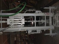
Jerky project cylinder action

   / Jerky project cylinder action #71  
If you limit the GPM's going to the ram valve to 2 or 3 GPM's you will not have a problem.

You should use the valve I suggested, to provide a regulated flow to say 3 GPM, and be done with it.

You can put this valve before any other valves, and the priority flow feeds the ram, and the excess flow goes to the hyd motors.

The out put from the priority flows goes to the IN port of the ram.

The output from the excess flow will go to the two spool hyd motor valve.
 
   / Jerky project cylinder action #72  
OK,, so what you are explaining is that this sort of valve has it's own relief built in? Then you would have anything back of that valve at the pressure of that relief and that means that for any of the excess flow to get through the valve, it would have to be at that pressure?

So a proportioning valve does split the flow between a working port and a return port but the pressure upstream of both will be subject to the relief of the built in portion of this valve? This makes sense as from one written discription, it seamed that there would be high pressure upstream of the working port and into the actuated device but no pressure upstream of the flow through port. This did not make sense to me as in my mind, any upstream pressure must be present to the working port load and the overflow port.
Did I explain it right? Quiz two for me, or maybe five?

Your second paragraph seems correct to me. The valve just functions to restrict the flow out the excess flow port until the required flow is reached out the controlled flow port.

The best way is to not worry about pressure with these valves, they're all about flow. All the pressure balances inside that make them work the user doesn't need to think about.
 
   / Jerky project cylinder action
  • Thread Starter
#73  
OK,

So both of you Gentlemen are telling me that while there is a bit of a relief setting to them, they actually internally will allow more or less pressure to the excess flow port based upon how much flow rather than pressure goes to the work port. Well, this changes things a bit. If I have these fine details right now it means that:

While my ram valve may need 600PSI, this valve special may pass the bulk of the flow at maybe 600 psi to allow the small amount to go to the ram valve to satisfy the 600 psi and max of maybe 3 gpm flow so the back pressure on the system does not have to be all at this valves working port pressure? Or maybe the back pressure would be what ever the ram vlave pressure would be? 600 PSI? In rethinking this, the upstream pressure has to be the needed working pressure and no less!!!!! It can not be 200 upstream if 600 is needed at the working port.

An earlier writer in his explanation left me with the impression that there would be no back pressure on the system through the excess port? That did not seam possible so I went with the thought of full back pressure of the relief valve more than a raw flow volume. It can be difficult to explain things in words even when you know what is going on.
 
Last edited:
   / Jerky project cylinder action
  • Thread Starter
#74  
JJ,

If I order one of these, I will get the one that is 1.5 GPM as I do not need any speed on this ram, just even slow flow. I will look into it tomorrow.
I would likely do this on the input side of the ram spool. Pipe the working port to the spool and the excess to the tank. This allows full flow at all times to go to motors and then after those, a split flow to the ram spool?
 
   / Jerky project cylinder action #75  
Hmmmm. Over the years I have operated a lot of hydraulic equipment from tractors on the farm to radial arm diggers and bucket trucks and I never had an instance that matched your situation. I have never encountered a hydraulic valve that I couldn't feather although some were indeed touchy.

Trouble shooting can often be facilitated by isolating sections of the system.

Have you tried using a different hose than is connected to the lift cylinder to make a loop between the in and out ports on the lift control valve? If nothing changes, you have eliminated any problem with the cylinder and hoses and the raising/lowering mechanism but if everything works great you've narrowed it down to the lift cylinder and hoses and the the raising/lowering mechanism.

The next step would be disconnecting the ram and cycle it in and out. If things are great then you might have a bind in the raising/lowering mechanism. If things remain the same look for a problem with the hoses or cylinder. Is there an unseen kink in a line? It's rare but sometimes the inner lining can become detached and fold over on itself causing a severe restriction to flow.

If nothing changes after the loop test, I would run two open ended lines from the lift control valve to a very clean bucket to catch the reusable oil and see what happens. If you still have a problem I would have to think it's in the valve itself and it would likely need replacing to make sure.

If you can't narrow it down after jumping through all those hoops...well, as they say, we'll cross that bridge when we get to it. :D
 
   / Jerky project cylinder action #76  
OK,

So both of you Gentlemen are telling me that while there is a bit of a relief setting to them, they actually internally will allow more or less pressure to the excess flow port based upon how much flow rather than pressure goes to the work port. Well, this changes things a bit. If I have these fine details right now it means that:

While my ram valve may need 600PSI, this valve special may pass the bulk of the flow at maybe 200 psi to allow the small amount to go to the ram valve to satisfy the 600 psi and max of maybe 3 gpm flow so the back pressure on the system does not have to be all at this valves working port pressure? Or maybe the back pressure would be what ever the ram vlave pressure would be? 600 PSI?

An earlier writer in his explanation left me with the impression that there would be no back pressure on the system through the excess port? That did not seam possible so I went with the thought of full back pressure of the relief valve more than a raw flow volume. It can be difficult to explain things in words even when you know what is going on.

The back pressure on the system and the pump will be equal to the pressure on the working port. You can't get more pressure out of this valve than you put in.

With 1.5 gpm it will take 7.6 seconds to fully extend the ram. You can buy the adjustable flow valves cheaper and set any speed you want.
 
   / Jerky project cylinder action
  • Thread Starter
#77  
If you limit the GPM's going to the ram valve to 2 or 3 GPM's you will not have a problem.

You should use the valve I suggested, to provide a regulated flow to say 3 GPM, and be done with it.

You can put this valve before any other valves, and the priority flow feeds the ram, and the excess flow goes to the hyd motors.

The out put from the priority flows goes to the IN port of the ram.

The output from the excess flow will go to the two spool hyd motor valve.

JJ,

I will use the parts that I ordered anyhow but if they alone do not solve this issue then I will order the valve you mention. I do understand that it would be best to proportion the excess to the flow from this valve to the motor spool and the priority flow to the ram valve then all should work:)
Thank you for your patience on this issue. I now have a better understanding of some of these devices. I did google the device but what I got to read was not too well done and the symbols were foreign to me?
 
   / Jerky project cylinder action
  • Thread Starter
#78  
The back pressure on the system and the pump will be equal to the pressure on the working port. You can't get more pressure out of this valve than you put in.

With 1.5 gpm it will take 7.6 seconds to fully extend the ram. You can buy the adjustable flow valves cheaper and set any speed you want.

Bigdeano,

Yes, both of you are right and I finally got the take on the propotioning valve. As such a valve would be more costly and bulky and I would still want to set a fill rate with the needle vlave, this is the way I am going at first along with the change in relief catradge to drop the pressure. If all goes well, I should have a pump that does not stall out and a slow filling ram that is not jerky or dangerous?

In fact to tilt the ram up the slow is good but to bring it back down, slowere is even better but the down speed would be much greater as the ram rod is 1.25 " so the fill volume is much less, much less. I am hoping the needle valve will regulate by default the down speed as well being that the oil has to exit through it to allow the ram to shorten up.

Parts to show up on wednesday and then a report on the saga?
Thank you all and keep the info coming:) I love to learn!

Gray---oh and this is my name---the color. Few believe me so I reverse the letters just for fun:)
 
   / Jerky project cylinder action #79  
yarg.

You seem hung up on the hyd pressure for the ram.

The ram is going to develop the pressure it needs to lift or use the load.

Whatever relief you put in the valve, will limit the load capability, or you will see the relief pressure if you hold the lever down long enough.

You could work that ram all day and never see relief pressure.

The hyd motors will develop the pressure they need for the load they are working also. If you are not working them hard, you may never see relief pressure.

Pressure is what it is, and is variable with load. Vary the load and the pressure changes accordingly..

Vary the GPM's of the pump and the speed of the motors will change accordingly.
 
   / Jerky project cylinder action #80  
velocity fuse..??

Do work for a manufacturer or distributor..?? or a custom thing

Sorry, long weekend. We are both, we build hydraulic packages and help with equipment building. The ones that I will be building will be custom for a pipe handler. I don't want anyone getting "happy fingers" so they will be inside a fitting at the cylinder base. just in case a line blows both cylinders will come down at the same rate. I cannot rely on P/O check because the unlock at different pressures and that would cause too much twisting and damage the unit. CJ
 

Tractor & Equipment Auctions

2010 Ford Edge SE SUV (A51694)
2010 Ford Edge SE...
2007 Ford E-450 Super Duty 16ft Portable Office Truck (A54814)
2007 Ford E-450...
2015 Peterbilt 320 T/A EZ-Pack Front Loader Garbage Truck (A54814)
2015 Peterbilt 320...
2011 Ford F-350 Knapheide Service Truck (A51692)
2011 Ford F-350...
JOHN DEERE 7210R TRACTOR (A51247)
JOHN DEERE 7210R...
2021 John Deere 333G Compact Track Loader, 390 Hours, High Flow Hydraulics, Ride Control (A55218)
2021 John Deere...
 
Top