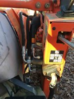
I also have attached the hydraulics schematic from the
L48 WSM, along with the page out of the WSM covering the hydraulic block. Hopefully you may be able to advise me on what the simplest option to add the TNT capability might be. I'm sorry....you're dealing with a rookie here and I've never read a hydraulic schematic before and I'm not sure I understand how the power beyond feature of the control valve and the tee you suggest work together....and I don't I fully understand power beyond, so I'd like to explain what I think you're saying and then you can correct me if I'm wrong. What you said about maybe not being able to use the rear QA's that supply the backhoe makes sense to me, but maybe you can tell from the attached schematic whether I can use those QA's or not.
So, presuming I cannot use the backhoe supply and would need to go off the FEL valve...
1. Am I right that the valve being used to activate the auxiliary remote (for the 4 in 1) on the FEL has the power beyond feature to provide full flow of hydraulic fluid to that 4 in 1 bucket.
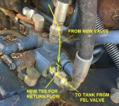
2. And are you suggesting, that one or both of the hoses going to that FEL remote would be disconnected from the valve, and replaced with a tee?
3. And then the tee would feed both the FEL remote and the new manifold for the TNT in the rear.
4. And are you saying that I would need some sort of manual shut-off to divert fluid to either the FEL remote or the new TNT remote, depending on which remote I needed to use?
By the way, if I just needed to flip a shutoff manually to shut off the front remote when I wanted to use the TNT, that would be perfectly fine. I don't use the front remote at all at this point. Getting a 4 in 1 bucket is on my wish list.
No problems with being a rookie. Everyone starts there.
Those are great attachments. Nifty Schmatics! Thanks for posting them! I think there's enough info there to work through & come up with the answer you want.
Right now I can't give you exact answers to your questions. I'll try, but the are not yet useful answers for building what you want..... Not yet they aren't. The problem is that we aren't yet speaking the same language about hydraulics and that's a sure fire formula for mistakes. But we're closer.
Here goes:
1. Am I right that the valve being used to activate the auxiliary remote (for the 4 in 1) on the FEL has the power beyond feature to provide full flow of hydraulic fluid to that 4 in 1 bucket.
JG, a better way to say that is: "The auxillary remote line (also called the 3rd function line) on the FEL is a form of power beyond circuit activated by a solenoid valve. Normally that solenoid valve is in the off position, and has constant fluid pressure flowing into it which is then constantly being internally routed inside the solenoid valve and sent back to the main fluid reservoir or "tank".
When power is applied to the solenoid, it's internal sliding valve moves into a different positon and now the fluid which before was simply going back to the tank is now diverted into a pressure line to run either an implement ..... or in your case it would probably run another control valve or group of valves. Since this Kubota has an "open type" hydraulic system we always have to provide a return flow, and that return flow will now be going back to the tank either from the implement or from a port on the bank of control valves always marked "R" for return.
And if you use that third function on the FEL your problem is solved. Except cosmetically. Since you already a pressure and a return line running right down the loader arm that is activated by a solenoid, You could mount a bank of as many valves as you want out there on that arm, hook directly to those lines on the loader arm - those hook to the pressure IN and return OUT on the valve bank..... and as far as the
L48 is concerned you are good to go.
All that remains is to run your controlled OUTPUT pressure and return lines from the top of the control valve over to whatever implement you are using. At this point you can run as many implements as you have control valves. One of the implements can even be yet another set of control valves!! Most valve banks have two or sometimes three handles. So if you need more handles to control more valves, that's what the power beyond is for. In theory there is no limit except for fluid losses and resistance you can run as many banks of control valves in series as you want. Each one feeds the next via the power beyond port....and of course each valve bank has to have its own return line back to the tank.
Now I'll admit this might look a little strange with control valves mounted on the loader arms and a forest of rubber hoses going to impements... but it would work.
For questions 2,3,&4 you ask: Are you suggesting, that one or both of the hoses going to that FEL remote would be disconnected from the valve, and replaced with a tee?and then the tee would feed both the FEL remote and the new manifold for the TNT in the rear?
And are you saying that I would need some sort of manual shut-off to divert fluid to either the FEL remote or the new TNT remote, depending on which remote I needed to use?
JG, I think that by now you see that you could do it that way. OR you could run the FEL remote from one of that plethora of valves we now have mounted all perched up there on the loader arm.
OK,,, OK.. you would rather do it some other way. Well, for that we need to get into those hydraulic schematics you so kindly posted.
And truly, learning to read hydraulic schematics is not that difficult....I guarantee you can do it in an evening. And I also guarantee that working our way through the
L48 schematic will take a bit longer. But it isn't hard, just arcane. It's arcane because because hydraulic schematics use what is called "functional symbology" where each line of each component's drawing is intended to show how the fluid is functioning at that point, and what pathways are open, shut, or transitional.
Here's a good simple example of what I mean: A control valve in schematic terms is shown as a rectangle composed of three squares. Eadh of the three squares has some lines inside the square which represent flow paths. IMPORTANT: ONLY the center square represents the normal or resting position of the control valve. To see what happens when the control valve is pushed or pulled, you mentally slide either of the outer squares so that it becomes superimposed on the center square. When you do that, those lines inside the square line up to show the flow of fluid in that condition. Makes sense??
So the trick to hydraulic schematics is that the simple geometric shapes of the components illustrate the FUNCTION of that component ..... but does so in a kind of shorthand that ultimately helps you to figure out what the component not only is doing, but can do.
I recommend you read through these three short basic tutorial modules on the Fluid Power Worlds web site.
It's easy reading, you can do all three in an evening & have time left over.
They are excellently written by Josh Cosford and Mary Gannon of Fluid Power World.
Fluid Power Products and News | Fluid Power World
Hydraulic Symbology 101
Hydraulic Symbology 102
Hydraulic Symbology 201 industrial directional valves
If those links don't work, the URL below will. It leads to the HS201 because the first sentence of HS201 contains working links to HS101 & HS102.
file:///Users/temporaryuser/Documents/%20%20%20%20%20_0%20__%20ROGERs%20EVERYTHING%20FILE/5__CBF%20ENGINEERING/Hydraulics%20and%20Hydraulic%20Engineering/Hydraulic%20Symbology%20201%20?20industrial%20directional%20valves.webarchive
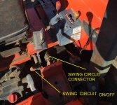
BTW, did you notice that in the bottom of your third sheet posted it mentions that the swing circuit can be used for powering other hydraulic implements when the backhoe is removed?? !
Enjoy!!
rScotty


")
