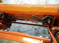
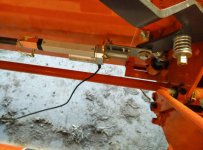
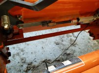
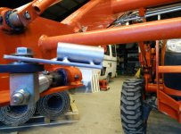
More tinkering. Upon closer inspection, the "nut" behind the levers where they connect to the pin has a built in bushing, so the handles could rotate. You can barely see the integrated bushing standing proud in the photo. I did a hack job grinding down a shaft collar (sandwiched it between 2 nuts on a bolt, stuck it in the drill press & hit it with the grinder) & enlarging the hole (die grinder as I didn't have a bit bigger than 1/2") on my mounting plate so the actuator mechanism could rotate as well. I still probably need to grind them a bit thinner. Really wish I had a lathe.
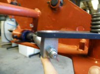
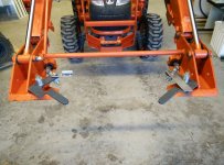
I redid some measurements & realized I was off quite a bit. Not sure how I managed that. Luckily things should work out due to how the levers go over center to latch down.
34.5" between the mounting bolts when the levers are all down
31.5" between the mounting bolts when the levers are half thrown, but the locking pin is still all the way down
27" between the mounting bolts when the levers are all the way up to retract the pins

7.5" of total motion, but about half of that is just the levers going over center so they lock. With the linear actuator in place to lock things, 4" of travel should get enough to cycle between max pin extension & retraction & not having to worry about an adjustable limit switch. Might be a good idea to go with a 6" actuator though. If I end up making an automatic door on the chicken coop for the wife, it might get my 4" actuator & I'll get a 6" or something. We'll have to see how this goes.
At any rate, going to make the mechinism highly adjustable. Will make a socket to pin on some all-thread to connect to the actuator. The other end I'll weld a nut or coupler to the mounting plate. Probably drilling a hole on one end & in the all-thread so I can put in a cotter pin or something to stop the all-thread from coming loose, yet be easily adjustable. Need to pick up a couple couplers at the store tomorow for the all-thread I scrounged up.


