My 30' x 40' tractor garage

/ My 30' x 40' tractor garage #1  

eepete

Platinum Member
Joined
Sep 30, 2009
Messages
963
Location
Efland, NC
Tractor
JD 4520, Kubota B21, JD 318
Here's a bunch of posts that show how a new tractor garage went together.

One common theme in this project is this: This is a Tractor Garage. It is not a shop. I'll do a lot of little servicing items here including fluid changes and small repairs. But I don't expect to do a lot of major repair or design work. That decision affects a lot of choices that were made. I consider a garage to be much cheaper than a shop. A shop would cost as much as a house per square foot, and would have a main room, dirty room (for welding), a paint area, bathroom, and some storage. A garage lets you park vehicles and do minor work on them.

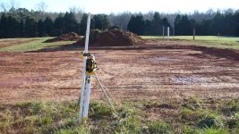
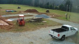
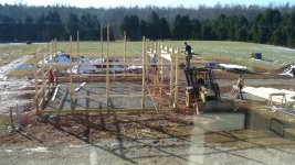
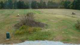
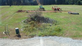
The area where the garage will go is south of the house. This is also where the garage on the house is. I have my electronics shop above the garage, and through a window have a good view of the entire site. The 1st picture shows the site, complete with left over top soil pile from construction of the house (which finished in late 2007).

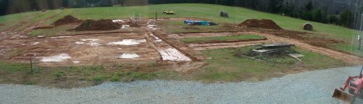
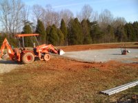
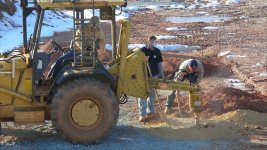
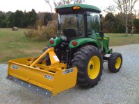
It is clear that I'll need to do a little earth moving on this job. I got a new tractor in the fall of 2009, which is part of why I needed a garage. What a great problem to have! It's a JD 4520 (60 HP, hydro, 50HP PTO, CAB). I've had a Kubota B21 since 1997 and love it. Clearly these two colors work well together. WhenI got a ball park quote on some of the grading cost (both clearing, leveling, and final grading) it was close to the cost of a box blade. No brainer there, the 2nd picture shows which way I went :thumbsup: !

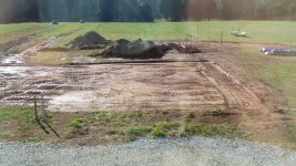
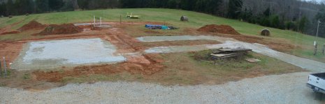
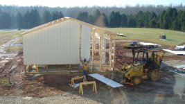
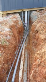
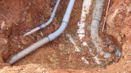
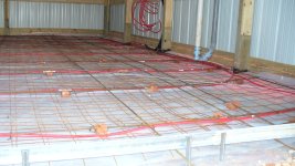
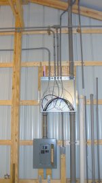
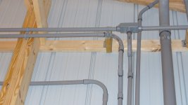
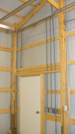
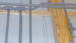
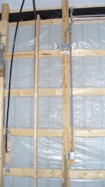
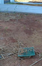
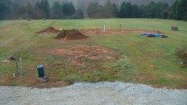
Another project was started before this- it's a photovoltaic power system (aka solar cells). This will be a grid tie inverter system, about 8KW DC, 6KW AC. I started this project before I had a firm date on when the building would show up. So the area in the 3rd picture is where the solar panels will go. I've scraped the top soil off for my 1st project with the box blade. Note also the conduit and 4x4 post in the lower left of the picture. These are pipes that go into the basement of the house so that when I got around to building a tractor garage, I could get back to the house. I also ran conduit out to where the PV array will go, you can see a drywall bucket on that. On the right, you see lumber that has been delivered for a small shed that will house the inverter for the PV project.
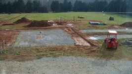
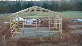
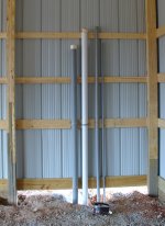
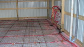
I got a lot done one the PV project before this- you can see conduit pipes sticking up. All the trench work, ground wires, and conduit for the solar project are in. When that project is done, I'll post that project.

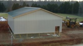
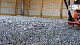
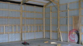
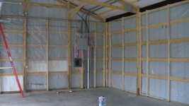
The building will be a Morton County Craft 30' x 40'. There is a build date of December 1st, so it's time to get the site ready. The building will go right where the top soil pile is, so the 1st order of business is to move that. It will be just behind/south of the new garage. Seems like there is no more pure form of seat time that moving a pile of something with a FEL.
 

Attachments

  • 1_before.jpg
    1_before.jpg
    511.3 KB · Views: 649
  • box_blade_and_4520.jpg
    box_blade_and_4520.jpg
    556 KB · Views: 1,458
  • 2_solar_topsoil.jpg
    2_solar_topsoil.jpg
    659.5 KB · Views: 651
  • 3_pile_moved.jpg
    3_pile_moved.jpg
    551.3 KB · Views: 716
Last edited:
/ My 30' x 40' tractor garage
  • Thread Starter
#2  
Time to course grade where the building will go. After my using the box blade to clear out the topsoil for the PV project, I decided that a hydraulic top link would be nice. When I got the JD 4520, I got the 3rd SCV so I could control it. Got the top link from CCM. Now to take the top soil off, add it to the pile, and do the course grading. I needed to cut down by 6" on the south west side (upper right in the picture) and fill by 8" on the north east (lower left by the conduits from the house). I put some of the dirt into the trenches left over from the geothermal system for the house. It takes 2 years for a 6' trench to settle all the way. You can see those as "mud streaks" on the left of the first picture.
On the outside of the cleared area, I went about 6' more out to get ready for final grad once the building was in. I had to use the sidelink to get that flat. I found myself wishing I'd listen to all the people who recommended the TnT for the tractor.

With the building site clear, I turned my attention to the approach to the garage. I took off about 4" of top soil, making yet another pile as you can see in the second picture. I had a stack of leftover pallets from construction sitting in the way. No job is ever done, is it?

The 3rd picture is a stitched shot of the entire job site. The 2nd story window really helps here. For those who have heard of the red clay of the south, here you go ;).

The 4th picture sets up the next step, the 8" of fill on the north east side. Got the laser level when doing the house and it was one of those "why didn't I get this sooner" things. Great for this sort of thing, and for drainage pipes.
 

Attachments

  • 7_laser_level_ready.jpg
    7_laser_level_ready.jpg
    678.1 KB · Views: 756
  • 6_course_grading.jpg
    6_course_grading.jpg
    760 KB · Views: 524
  • 5_course_driveway_grading.jpg
    5_course_driveway_grading.jpg
    565.1 KB · Views: 608
  • 4_course_building_grading.jpg
    4_course_building_grading.jpg
    636.8 KB · Views: 661
Last edited:
/ My 30' x 40' tractor garage
  • Thread Starter
#3  
In the first picture you see the laser level in the middle of the building,I put a ring of crusher run so that it was just outside of the building perimeter. Then I will fill with washed stone (1/2 " to 3/4" sized). The crusher run keeps the washed stone from "squishing out" as work progresses.

The 2nd picture shows the garage driveway work. I put down some landscape cloth, then a thin layer of pea gravel, then railroad balast, then crusher run. You can see the washed stone that I had delivered, it's the next step. It will be used to fill the garage area, and to cover the crusher run.

The 3rd picture is another stitched shot of the project. You can see the fill where the garage will be. That is now level to within about an inch. I've not dealt with the problem of the aprons and the level of the driveway, so there is a muddy no mans land between the garage and the drive leading to it.
The long, straight section is there so that the section that comes off the existing driveway is a clean exit, different from the garage. The gravel you see at the bottom of the picture is off of the existing garage on the house. I also wanted a long area so I can park tractors there if I need space to do some small project in the garage. A straight approach also means I am less likely to take out the side of the garage. All entry and exit are straight on approaches. Finally, this is a good area to blow off the grass after mowing. This is also the high spot of this area of the field.
 

Attachments

  • 8_gravel_leveling_building.jpg
    8_gravel_leveling_building.jpg
    578.3 KB · Views: 1,132
  • 9_gravel_leveling_driveway.jpg
    9_gravel_leveling_driveway.jpg
    544.3 KB · Views: 856
  • 10_gravel_done.jpg
    10_gravel_done.jpg
    668.5 KB · Views: 613
Last edited:
/ My 30' x 40' tractor garage
  • Thread Starter
#4  
Well, now it's time to get my schist together :laughing:. So I rented a compactor. Made a huge difference, especially on the crusher run. I also packed the driveway, which was a big win. When I drove the tractor on it, it stayed put after compaction.
 

Attachments

  • 12_compaction_done.jpg
    12_compaction_done.jpg
    714.4 KB · Views: 712
  • 11_compaction_time.jpg
    11_compaction_time.jpg
    369.2 KB · Views: 946
/ My 30' x 40' tractor garage
  • Thread Starter
#5  
The building materials were delivered, but it was not until around December 10th that weather allowed for construction. This was the worst winter in a long time for doing outdoor stuff. From October to February, we never went more than 5 days without rain or snow. I had a lot of days where what took me an hour to do in the mud would have been a 20 minute job in better weather. But the weather looked good, and the crew from Morton showed up to put up the building.

The 1st picture shows them drilling down 4.5' 14" diameter for the posts. The hole they are digging in this shot took as long as all the other holes put together. If you look behind the tractor, you'll see the spoil piles of clay. This spoil pile is yellow. This is a hard type of clay-rock that runs in viens on the property. My B21 and I have spent 3 hours going 4' when I've hit this stuff going to a depth of 2.5'. It's backhoe, manual mattox, say "golly gee" a few times, and then backhoe. They really had to dig here. So the middle post on the west side is basically drilled in rock. That's good, thats where any shear wind will come from.
Oh yeah, the faces have been blurred out. It was a great crew, we got along well, I just don't like posting pictures of people without their permission.

The 2nd picture shows the concrete truck showing up. The posts had a metal jig on the bottom that insured that the post was setting up on about 8" of concrete. Then about 16 to 20 inches of concrete cover the bottom of the post. All the strings are setup and using those and levels the posts are set.

The 3rd picture shows the end of the 1st day. The posts are set.
 

Attachments

  • 13_post_holes_dug.jpg
    13_post_holes_dug.jpg
    939.9 KB · Views: 847
  • 14_post_set.jpg
    14_post_set.jpg
    347.4 KB · Views: 851
  • 15_1st_day_done.jpg
    15_1st_day_done.jpg
    383.7 KB · Views: 771
Last edited:
/ My 30' x 40' tractor garage
  • Thread Starter
#6  
Now the building gets framed. The 1st picture shows that in progress.

The 2nd picture shows the completed framing, day 2 is done.

The3rd picture shows the start of siding on the 3rd day. The tractor is quite something. It's a FEL and PHD, and has a scaffold that can have it's height and tilt set hydraulically. This specialized tractor is the key is the perfect complement to the crew's abilities. No, I don't have anything to do with Morton I was just amazed at how smooth it all went. I think they've done this a time or two.

The 4th shot is near the end of the 4th and last day. All that is left is the Wainscotting siding, facia and soffet. The concrete and garage doors are done by subcontractors hired by Morton.
 

Attachments

  • 19_siding_roof_done.jpg
    19_siding_roof_done.jpg
    473 KB · Views: 1,232
  • 18_siding_starts.jpg
    18_siding_starts.jpg
    514.5 KB · Views: 907
  • 17_framing_done.jpg
    17_framing_done.jpg
    722.7 KB · Views: 1,281
  • 16_framing_day.jpg
    16_framing_day.jpg
    631.5 KB · Views: 1,102
/ My 30' x 40' tractor garage
  • Thread Starter
#7  
Well now it's going to get ugly. It's about 35 degrees out, wind blowing, it's rained, and the mud is either wet or frozen. It's time to dig up those conduit stubs and re-work them into the building. A bit of backhoe time, but a lot more crouching in a ditch in the cold and wet with a shovel. This is kinda the opposite of the "move the topsoil pile" seat time experience.

The 1st picture shows the conduit after it's been uncovered.This is down about 3 feet deep. There is a 3" electrical conduit, and 3" drainage PVC for other stuff, another 3" PVC for more future expansion beyond any tractor garage, and two smaller conduits that go to the solar project area.

The 2nd picture shows the final result of getting these conduits up into the building. I dug to within about 1.5' of the building with the backhoe. It was one of those "push it too far and put the bucket in the building and you'll be kicking yourself" moments. The last 2' of excavation I would do by hand. It turned out to be a big chunk of soapstone, so it was me and the mattox tighter again. All this took about 2 days. The end depth was 3'. You can see the horizontal ground rod in the trench. BTW, all this conduit work and all of the building was permited and inspected by the county, so everything is on the up and up.

The 3rd picture shows the reworked ground area we saw in the 1st picture. I pack the dirt and gravel around the pipes to reduce trench collapse in the following year.

The 4th shot shows the conduit coming up into the building. I've put another round of wood below the 2x6 band that Morton put on the building. This is in the 8" of fill area on the north east side of the project. There is going to be 4 more inches of gravel added by Morton before the concrete. so the cut area will have 4" of stone under it, and the fill area will have about a foot. Once the conduit was in, I put in the last board, and then on the outside put in a layer of crusher run to support it so the stone would not push out from under the building. The final product hides the mess it was to get it done, from the cold to the well diggers patoot problems.

We had some rains and the fill around the colums sank a bit. I further compressed with a sledge hamer, and then put about 4" of stone on top of it which I then compressed with the sledge again. This will leave a 1 foot collar around each post when the pad is poured. Between that and the concrete base, the posts are well anchored even though it's not solid concrete fill.

I did not do the rebar in the post to tie it to the pad. The post is in 16" of concrete at the base, and a foot at the top. Pushing a post in would be about impossible. And if it's being pushed out, the building has been compromised already. I'll be wrapping the conduit so the slab can shift or settle a bit. Similarly, if the slab settles a bit (I'm talking 1/8 to 1/4" or so) it can slip down the post OK and the ground supports the slab, not the post. I'll let you know over the next 30 years how that works...
 

Attachments

  • 20_conduit_dig.jpg
    20_conduit_dig.jpg
    563.7 KB · Views: 699
  • 21_conduit_run.jpg
    21_conduit_run.jpg
    659.4 KB · Views: 652
  • 22_conduit_final.jpg
    22_conduit_final.jpg
    691.2 KB · Views: 611
  • 23_conduit_inside.jpg
    23_conduit_inside.jpg
    282.2 KB · Views: 1,085
Last edited:
/ My 30' x 40' tractor garage
  • Thread Starter
#8  
The concrete subcontractor put in the 4" of washed stone. It was leveled such that it would make a 5" pad. The standard pad is 4", I paid a bit extra to get a 5" pad. This would put the bottom of pad about 1" below the 1st band of boards that came with the building (or, about 1" below where the Morton band and the wood I added meet).

I asked if they were going to compact the stone. They said it was self-compacting. So I said "Well then, I guess it won't be a problem if I rent a compactor and beat on it then, will it?" So I did. If you look closely you can see the difference between the stone as it fell, and the compacted stone. I probably picked up about 1/2 to 3/4" by compacting the stone, making the pad just under 6" deep.

You can also see the foam wrap on the conduit.
 

Attachments

  • 24_final_gravel_compact.jpg
    24_final_gravel_compact.jpg
    585.6 KB · Views: 2,039
Last edited:
/ My 30' x 40' tractor garage
  • Thread Starter
#9  
The Morton spec for concrete is fiber fill or mesh. I went with mesh, and told Morton I'd be putting in some rebar. They were OK with that, and the flatwork contractor just cut the mesh and left it outside. After the termite treatment, I put down their plastic then I put down another layer of 6 mil plastic. That meant I could walk on the plastic and not puncture the top layer. A lessoned learned from building the house.

The 1st picture shows what things looked like after a few days. At the last moment, I bought some PEX pipe so I could heat the pad. The #3 rebar and the PEX pipe are on a 3' square pattern. Brick pieces hold up the rebar and mess, and the pipe is run with this rebar. I put tape around the PEX where it would contact the brick so it wouldn't be damaged during the pour. The pipe is the special oxygen barrier type you are supposed to use for this sort of thing.

The 2nd picture is another view of this from a higher angle. I connected all the pipe together and put air on it (100 PSI) to see if it held. It did, and then I left the pressure at 60 pounds all during the pour so I could tell if there was a problem (not that I had any great plan if something went wrong, but I did have some splices and left over pipe).

The two pipes you see on the right are a power pipe and 3" drain PVC that go to the inverter shed. I made the inverter shed bigger than it needed to be so I could put the air compressor in there. It will be very nice to do things in the garage and not have to be in the same room as the air compressor.

When we got the inspection, I got a surprise! I was asked if this was a garage or shop. I proudly said "It's a garage!". Well, it turns out that if you build a garage you need either a drain pipe or a slight slope to the floor. Shops have a flat floor. Putting in a drain pipe would be hard with all that rebar down, so I decided to bring the pad up in the back of the building by 1.5". You can see the line along the bottom board, and see how it's lower in the front than in the rear. So the 5" pad went to 5.75" (due to compaction), and at the back it's up to almost 7" thick (due to the slope).

One other comment on the PEX pipe. There is no insulation in the floor. My goal here is _not_ to heat the room to 65 degrees, but to have the pad at about 50 degrees which is ground temperature around here in the winter. That's the temperature of the water that comes out for the geothermal system. So some day as yet another project (I have a friend who respectfully and nicely calls me "The Project *****") I want to try a solar hot water and PV panel to automatically heat the pad in the garage. If that pad is near 50 degrees, that will be a huge success. Note also that the pipe, especially near the back of the garage, is down about 4" from the top of the pad. As I understand it, for radiant heat the pipe really wants to be 2.5" from the top. So we're back to "It's a garage" and a garage at 50 degrees in the dead of winter is a huge win. And the rebar is down way below the middle of the pad, which is where it should be to have it work. So in the case of a shop with a floor that was meant to support lots of weight, the rebar would be at 1/3 of the way from the bottom, and the radiant heat pipe would want to be 2.5" from the top. That and the need to insulate the pad make it a lot more work and cost. Did I mention this is a garage?
 

Attachments

  • 25_rebar_wide.jpg
    25_rebar_wide.jpg
    448.2 KB · Views: 1,187
  • 26_rebar_manifold.jpg
    26_rebar_manifold.jpg
    424.9 KB · Views: 1,937
Last edited:
/ My 30' x 40' tractor garage
  • Thread Starter
#10  
A Pour Day

What other sort of adventure can you have where a pour day has concrete results ? :D

1st shot is the concrete going down. I was pulling up the mesh, as were the workers. You can also see in the lower right a height stake they put in.

The 2nd shot shows the rebar and mesh for the 8' apron. You can see the keyway at the building edge. Four pieces of #3 rebar go into the pad and will keep the apron attached. A pieces of #4 (1/2") rebar is right up agains the keyway (6" from it), and the same is true on the other side. Since this is a maximum stress point, I beefed up the rebar size and spacing here.

I messed up :mad:. I thought the 8' was from the _inside_ edge of the building, it was from the outside. So when I dug the apron and made it for a 2" drop over 8', I came up short. They measure the apron's 8' from the outside of the building. So the apron thickness is 5" except for the last foot, where it tappers down to 3.5" (the 2x4 height). I tossed in an old bent up #4 rebar in hopes it would help. The form for the apron was done after the garage floor was poured. So I had a problem that was discovered in the middle of a pour and cure process. That's about as worst case as it gets. Worker were great about hitting the shovels and digging out the extra foot or so to keep the job moving.

3rd shot is the smoothing. The temperature that day was 65 degrees, and we had low humidity. A good day to pour for being in the winter. They were there until 11:00 that night working it. It got down to 38 that night. I had one crack in the apron where I didn't have enough blankets to cover the last 2'. Glad I had the rebar and mesh in there- the crack should stay put.

The 4th shot is something I had them do at the door. I also had to play with the heights to keep my 5" pad (minimum). A little extra digging out and then working the gravel pad. I had them cut down about 1" at the door so that water would not blow in. The doors face west, so they get hammered in a heavy rain. It all worked great. I had this done with a 2x6 at the old house, but the step bump was really annoying, particularly if you push something in by hand. The sloped drop down is a big win. The garage has two doors, a 10' x 10' and a 12' by 8.5' high. The 8.5' high means the bump up is not a problem for the tractor FOPS or Cab, and is not a problem with the apron 2" drop and final grading. No water incursion, just drive in, life will be good.
 

Attachments

  • 49_concrete_cut.jpg
    49_concrete_cut.jpg
    171.3 KB · Views: 928
  • 29_concrete_smooth.jpg
    29_concrete_smooth.jpg
    388.2 KB · Views: 1,057
  • 28_apron_rebar.jpg
    28_apron_rebar.jpg
    623.1 KB · Views: 790
  • 27_concrete_down.jpg
    27_concrete_down.jpg
    431.1 KB · Views: 738
Last edited:
/ My 30' x 40' tractor garage
  • Thread Starter
#11  
With the pad poured, it's time to do the electrical. This took way to long, and being a one man band didn't help. I brought three circuits from the house. A 15 amp light circuit that is on the whole house generator, a 20 amp outlet circuit also on the generator, and a 100 amp sub panel circuit that comes off of the breaker box _before_ the transfer switch (so it is not on the generator).

The 1st picture shows the 3" conduit from the house going into a 24" square junction box. You can see the big #2 wires going down to the breaker box. A pricing quirk at the big box stores had the #2 wire cheaper than the #4 wire, so I went with #2 including the ground. I love overkill. You can also see a disconnect switch for the two circuits off the generator just to the right of the breaker panel box. The 2' box and disconnect is where working with my buddy the electrician helped. I'm sure that most inspectors could help too, I've had ours out for a consultation when I'm at a point like this and it's been very helpful. No point in doing something twice when you could have asked and got it right the 1st time.

The 2nd picture is a close up the area above the big honking 2' box. Some pipe went on the outside of the poles, some on the inside. I probably could have heated and bent the conduit instead of using the pre-formed pieces, but it was easy to use the pre-formed and helped me in one man band mode. The big 2.5" goes to the other side of the garage both to get power to the future air compressor in the inverter shed, and as a general way to get "stuff" over to the other side for any future escapades.

The 3rd shot shows the switches for the lights at the door. There is also a box for low voltage for a phone and door switch for security. You can see a pipe going down by the hinge of the door- this is for an outside light on a motion detector.
The four switches: The 1st switch goes to 2 60 watt incandescent flood light bulbs. This lets me get a little light so I can see to get something from the garage. The 2nd switch goes to 7 24 watt compact fluorescent flood light bulbs for when I really need to light the place up. Since they take a while to get to full brightness (more time if it's cold), I will only use these if I'm going to be in the building for a while. All compact fluorescents are like well pumps. The may run forever but they only start so many times. So being able to choose between the cheap incandescent and the fluorescents is a win. The next two switches are outside flood lights, a set on each side of the building.

The 4th shot is a close up of the are above the switches, showing the two drops to the boxes. Yes, I could have just used one drop and then connected the boxes. There are many ways to run the conduit. I suspect if I did it for a living it would be completely different. The best feature of all this conduit and wiring? It works :)

Why conduit over just stapling romex to the wood? Well, I do like overkill. I also liked the physical protection I get. And if I have to add something else after everything is buttoned up I can pull more wire in conduit. Finally, and this is very fuzzy and subjective, I like the 10,000 volt insulation of the conduit in case the building gets hit by lightning. Can't prove it would work, but it can't hurt.
BTW, the rebar in the pad has a wire that comes up and ties to the AC ground.
 

Attachments

  • 30_conduit1.jpg
    30_conduit1.jpg
    369.4 KB · Views: 698
  • 31_conduit2.jpg
    31_conduit2.jpg
    294.1 KB · Views: 363
  • 32_conduit3.jpg
    32_conduit3.jpg
    289.2 KB · Views: 417
  • 33_conduit4.jpg
    33_conduit4.jpg
    287.8 KB · Views: 369
Last edited:
/ My 30' x 40' tractor garage
  • Thread Starter
#12  
Next step is to prep for insulation. I'm using the spray foam (iscyonene (sp?)). Now I could just spray it on the metal, and it would be just fine. But if you had to replace a piece of siding, the foam would come out with it. So I decided to put plastic up against the bottom run of metal siding (the wainscoting) since that's what I'd be more likely to run into. Then I decided to make the building more sustainable and do it all. That way, in 30 years (I wish) when I exit horizontally, the next user can replace or upgrade the building siding and the insulation will stay put. It's green two ways. (1) Longer building life and the metal siding is very recyclable, and (2) if the next owner looks at changing the siding out and sees/learns of the plastic, it's one less reason not to by the place. My nieces and nephews will thank me some day as they blow our money. I like any green project as long as it's green two ways. And the original "you can fix it without bunging up the insulation" is good stuff too.

The 1st picture shows a prepped area. At 1st, I tried a vertical sheet. but I had to put in blocks of wood to give the insulation something to grab on to. So then I went horizontal so that all the horizontal purlins would be exposed and the foam would stick to it. I put some extra screws in the wood to help the insulation stay put. Behind the big 2' electrical box, I put hard foam insulation, same for the breaker panel and a few other areas that would be blocked and hard to get the foam into.

The next picture shows the area between the garage doors. On the left, you can see the water line I ran in the 3" PVC from the house for a hose bib. You can also see the 2x6 I added between the Morton post to help put up a wood wall cover later. I had to add these all around the building. You can see a copper pipe for compressed air running down that added wall stud. Then you see one of 4 outlets. I already mentioned one on the generator, there are 3 more 20 amp outlets in the building. Finally, one of the lights are shown. Simple, same bulb I use everywhere for outside lights. Note also that I covered up the soffit vent so that the foam would not get UV exposure from the outside. The foam degrades quickly when exposed to UV.

The 3rd picture shows the south east corner of the garage. I added blocking for shelf brackets. This is where a lot of implements will be stored, many on dollies. Having a shelf at the 6' level, above the implements, give me more storage room. Again the soffit vent is blocked and you can see the 3rd set of inside flood lights.
 

Attachments

  • 36_plastic3_shelfblock.jpg
    36_plastic3_shelfblock.jpg
    355.7 KB · Views: 613
  • 35_plastic2.jpg
    35_plastic2.jpg
    326 KB · Views: 535
  • 34_plastic1.jpg
    34_plastic1.jpg
    365 KB · Views: 707
Last edited:
/ My 30' x 40' tractor garage
  • Thread Starter
#13  
With the floor covered and everything masked, it's insulation time!

Three shots of blowing in the insulation.
 

Attachments

  • 37_insulate_1.jpg
    37_insulate_1.jpg
    290.1 KB · Views: 818
  • 38_insulate_2.jpg
    38_insulate_2.jpg
    334.1 KB · Views: 634
  • 39_insulate_3.jpg
    39_insulate_3.jpg
    415.6 KB · Views: 781
/ My 30' x 40' tractor garage
  • Thread Starter
#14  
Next step was to put up the wood walls. The first two feet are pressure treated 1/2" plywood at the bottom. Then I put in either 7/16 OSB or 3/4 plywood above that (next 4' of height). I used the 3/4 plywood where I thought I might be attaching things to the wall such as hooks, holders, etc. I used 7/16 where I would have shelves. I was originally going to use a 3/8 panel, but the 7/16 was only a buck more a sheet. With 4' between mounting points, that would have been a disaster. Don't use anything smaller than 7/16. Above that, for the top 4', was all 7/16 OSB. All this went to a height of 10', the same as the tallest door. This provides both physical and UV protection.
 

Attachments

  • 40_boards_1.jpg
    40_boards_1.jpg
    444.2 KB · Views: 1,034
Last edited:
/ My 30' x 40' tractor garage
  • Thread Starter
#15  
Paint time!

The exposed insulation needed to be painted so that it would not degrade. So I painted the insulation and walls white. The white really helps with the light in the place. Yes, it will get dirty and dingy over the years but it's a garage, get over it :).

The last shot shows the entrance and north wall. A little paint, a little wood, and things are starting to look pretty good. I also sealed the concrete floor since we finally had a day with temperatures and humidities in the right range.
 

Attachments

  • 43_paint_done.jpg
    43_paint_done.jpg
    386.6 KB · Views: 1,039
  • 42_paint_2.jpg
    42_paint_2.jpg
    382 KB · Views: 685
  • 41_paint_1.jpg
    41_paint_1.jpg
    437.9 KB · Views: 626
/ My 30' x 40' tractor garage
  • Thread Starter
#16  
Here are some stitched shots of the interior. Not a good stitch, but gives some idea of what it's like.
 

Attachments

  • 45_pan_ins.jpg
    45_pan_ins.jpg
    87.9 KB · Views: 610
  • 46_pan_paint.jpg
    46_pan_paint.jpg
    56.1 KB · Views: 567
/ My 30' x 40' tractor garage
  • Thread Starter
#17  
Here's a controversial one. I grounded the outside of the building into a ground rod. I used 1/2" stainless steel strap. It is connected to the ground rod with a stainless hose clamp. This is better than 90% of the buildings with no grounding where you take your chances, and not as good as "real" lightning rods into big wires going to lots of ground rods. I've seen the results of lighting hits on buildings with all my firefighter work. This lets lightning find ground without having to make some annoying couple foot arc and all the consequences thereof.

DO NOT DO THIS. There's my disclaimer.

Part of why I have all my wiring in conduit is that the conduit provides about 10 Kilovolts of insulation. Since that's all on the inside of metal box, if I provide a way on the outside for the charge to go to ground, I have a better chance of not having the strike get into my electrical. The outside lights are also fully insulated from the shell. Again, no guarantees, DON'T DO THIS, I'm just trying to improve the odds if I have an average strike. I'm pulling rank with my electrical engineering experience and saying don't try this at home. Do what I say, not what I do. Betcha I still get flamed on this one...
 

Attachments

  • 47_lightning_ground.jpg
    47_lightning_ground.jpg
    338.4 KB · Views: 748
Last edited:
/ My 30' x 40' tractor garage
  • Thread Starter
#19  
I put yard drains in by the aprons. This is where I had the 6" cut during grading. The drains are 2" lower than the ends of the aprons. When I do the final grading and landscaping, this will give the water a way to get away from the building where I've cut out a low spot. This is a 3" PVC smooth drain pipe with the 1/4" per foot drop. Of course, this was all in place before the pads were poured.
The other three sides of the building will have a grade so that the water drains away from the building. That's where the Tnt and Boxblade do their thing. This is why on the south side during initial grading I took a 6 foot cut beyond the building perimeter. I can use the box blade to make a 12' 'V' for drainage that works into the grade. Nothing to clog, mow to maintain.
 

Attachments

  • 48_yard_drain.jpg
    48_yard_drain.jpg
    417.3 KB · Views: 522
Last edited:
/ My 30' x 40' tractor garage #20  
Here are some stitched shots of the interior. Not a good stitch, but gives some idea of what it's like.

Excellent job. Thanks for the details and photos.

Just a suggestion:
Your images take too long to load.
The Microsoft Power Toys website has a utility for Windows Explorer and Windows Libraries (in Windows 7) called "Image Resizer" that allows you to easily change the size of an image.

Microsoft PowerToys for Windows XP

I think you'll like it.
 

Marketplace Items

2021 CATERPILLAR D5 LGP HIGH TRACK CRAWLER DOZER (A60429)
2021 CATERPILLAR...
Massey Ferguson 9250 (A61307)
Massey Ferguson...
2021 CATERPILLAR 259D3 SKID STEER (A60429)
2021 CATERPILLAR...
INGERSOLL RAND  G25 GENERATOR (A58216)
INGERSOLL RAND...
UNUSED IRANCH MINI EXCAVATOR QUICK COUPLER (A60432)
UNUSED IRANCH MINI...
2017 Yale GLC050VX 3,500 lb LPG Forklift - Powershift, Aux Hydraulics (A61306)
2017 Yale GLC050VX...
 
Top