johara1 said:
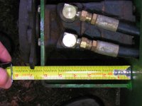
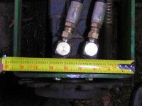
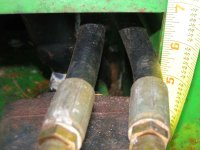
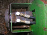
KenT,they are all the same rotation,reverse rotation. means, forward and reverse.just put the lines on the way you take them off.i had it up on jack stands to run it and check for rotation and leaks,they all turned the same way.again you will need a case drain.i see on char-lynn s series they have a1" taper shaft#18 on output shaft.
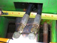
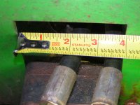
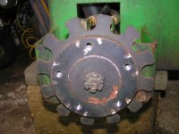
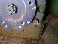
the grinding i did was with a 4 1/2" grinder with a .045 cutoff wheel and new grinding wheel to finish it.i took about 3/16 off each side,top high enough. be prepaired,pt. isn't to fussy on there jigs the two front ones went right on after i cut the holes bigger but the back two took a lot of work to fit them in.the plate on the bottom was too high and wouldn't let the motor line up with front bolt holes,but you can do it.
Thanks for the reply -- and the tips. I still don't have the price quote back on the "special order" Model S motors that I spec'ed out. I hope they're as competiitively priced as the quote they gave me on the Model W's. I'm expecting them to be more expensive, I just don't know how much.
Here's what I spec'ed:
- 18.2 ci (code 182)
- 4-bolt std mounting face (code FA)
- 1" tapered shaft with woodruff key and nut (code 18)
- 1/2" SAE threaded ports (code AB)
- No case drains (more to follow) (code 0)
- High pressure shaft seals (code 07)
- Low speed valving (code AB)
- Black paint (code A)
Every other part of the 25-position model code buildup was either the default or not applicable.
I talked to the Char-Lynn Tech desk (the distributor referred me directly there) and asked him several questions. One was specifically about the case drains, since my current wheel motors don't have them. He said plumbing in case drains would be the best way to go, for sure, since they would likely extend the life of the motor, but they weren't essential on a motor with a max operating pressure (continuous) of only 1500 PSI, and that isn't continuously running. The examples he gave of where they're most needed is on things like conveyor belts...
As an alternative to all the plumbing I'd need to install case drains, he steered me to the High Pressure Seals option. These seals can withstand up to 1500 PSI of internal pressure (on the S motors, differs on other models) should pressure build up in the motors. The application description reads:
- Increases ability to handle high-pressure spike conditions
- Eliminates the use of case port lines in applications with intermittent extreme operating conditions
- Can be an effective alternative to additional port plumbing
So, to simplify my life and hold the total cost of the conversion down (since I don't currently have case drains) I went with the High Pressure Seals option instead. Since I'm running reversed wheels and loaded tires, reducing the possibilty of blown or leaking seals sounded good to me... Note that this is a very expensive "kit option" to add later, since you must also replace the motor's shaft because of how it's machined so that the internal pressure closes the seal.
He also steered me toward the Low Speed Valving option. This optimizes the motor for operation under 200 rpm with increased sealing and tighter clearances. It makes the motor more efficient (less leakage and consequently less internal pressure buildup) and provides smoother operation at low speeds...
Finally, he confirmed that a geroler is just as efficient running backwards as forwards, so shaft rotation was not an issue -- just swap the lines to make them turn in the direction you want. He said this option was for applications where you couldn't swap the lines, for whatever reason....
Well, that's what I spec'd... I hope to have the "price-tag" tomorrow. I'm sure it'll likely be a special order, which could take up to 40 days to be delivered due to factory lead time.
Thanks again for all the help, everyone!
") ) that the current system -- with two series circuits -- is likely limited by relief valves to 1500 PSI total. Without that pressure drop from series circuits, the system would go to 3000 PSI, theoretically, but that is limited by the relief valves. That was the foundation of the whole "Stray mod" concept. But, these White wheel motors couldn't stand those types of pressures.
) that the current system -- with two series circuits -- is likely limited by relief valves to 1500 PSI total. Without that pressure drop from series circuits, the system would go to 3000 PSI, theoretically, but that is limited by the relief valves. That was the foundation of the whole "Stray mod" concept. But, these White wheel motors couldn't stand those types of pressures.