Photos of Third Function Valve Project

   / Photos of Third Function Valve Project #1  

Gordon Gould

Super Member
Joined
Apr 1, 2007
Messages
6,260
Location
NorthEastern, VT
Tractor
Kubota L3010DT, Kubota M5640SUD, Dresser TD7G Dozer
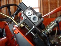
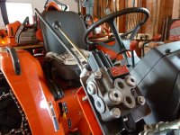
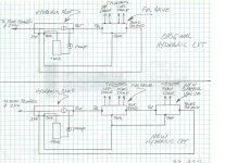
I wanted to install a new valve to control my grapple and get it off of the rear remotes so I can use them for TNT. I wanted the valve control to be near my FEL lever. Last Nov teg posted a very nice discription of a similar project he did. I stole alot of his ideas. THANKS teg. This is a link to his post

http://www.tractorbynet.com/forums/...7948-instructions-add-extra-spools-l2800.html

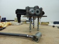
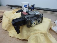
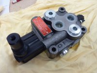
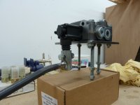
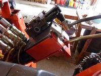
I started by buying a single spool DA 8 gpm Prince valve fropm Surplus Center.
Prince # MB11B5C1 DA.
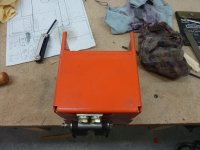
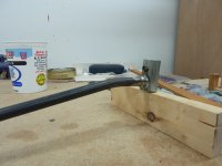
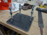
I built a mounting plate for the valve from a piece of 5 1/2" X 6" 1/4" plate.
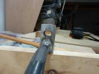
I drilled and tapped 3 holes for 3 3/8" mounting studs. Jam nutted and welded them.
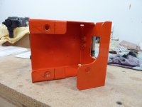
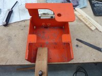
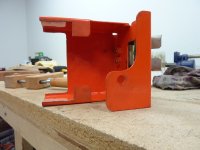
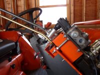
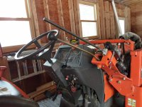
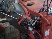
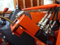
Drilled 3 5/16" holes to mount the valve, and one hole in the corner for a heavy sheet metal screw to attach to the orange cover. I am going to mount the valve and plate on the FEL linkage cover. Photos: Linkage Cover, Cover Removed, Base Plate.
 

Attachments

  • Cover_On.JPG
    Cover_On.JPG
    460.2 KB · Views: 1,106
  • Cover_Removed.JPG
    Cover_Removed.JPG
    455.9 KB · Views: 974
  • BasePlate.JPG
    BasePlate.JPG
    424.6 KB · Views: 851
Last edited:
   / Photos of Third Function Valve Project
  • Thread Starter
#2  
I wanted to be able to remove the linkage cover when I was done in case I had to get in there. So I cut off the two rear mounting tabs and cut a chunk out of the top. I used the two rear cover mounting screw holes in the FEL bracket for 2 of the the 3/8" studs. The bottom cover screw is still used from under neath.
Photos: Cover Cuts.
 

Attachments

  • Cover_Cut_4.JPG
    Cover_Cut_4.JPG
    350.2 KB · Views: 333
  • Cover_Cut_2.JPG
    Cover_Cut_2.JPG
    458.1 KB · Views: 305
  • Cover_Cut_3.JPG
    Cover_Cut_3.JPG
    427.8 KB · Views: 293
  • Cover_Cut_5.JPG
    Cover_Cut_5.JPG
    344.3 KB · Views: 326
Last edited:
   / Photos of Third Function Valve Project
  • Thread Starter
#3  
I turned the handle housing on the valve around 180 degrees so that it was pointing downward. Mounted the valve on the base then put the assembly on the tractor. Two of the studs go into the rear cover holes, the third goes into a hole I drilled in the outside corner of the FEL bracket. Photos: Valve, Housing 180, Valve & Plate, On Tractor
 

Attachments

  • ValveOnTractor.JPG
    ValveOnTractor.JPG
    411.2 KB · Views: 666
  • ValveOnBase.JPG
    ValveOnBase.JPG
    438.4 KB · Views: 416
  • ValveHandleHousing180.JPG
    ValveHandleHousing180.JPG
    427.9 KB · Views: 337
  • Valve.JPG
    Valve.JPG
    398.7 KB · Views: 428
Last edited:
   / Photos of Third Function Valve Project
  • Thread Starter
#4  
I made a lever arm from a 3/4" X 1" bushing and a 18" length of 1/2" rod. I put an oblong hole in the bushing to allow side motion to the lever. This way it can move left and right to follow the FEL lever when I curl and dump. I bent the rod to match the angle of the FEL lever arm.
 

Attachments

  • LeverArm_1.JPG
    LeverArm_1.JPG
    461.3 KB · Views: 324
  • LeverArm_2.JPG
    LeverArm_2.JPG
    320.5 KB · Views: 364
  • LeverArm_3.JPG
    LeverArm_3.JPG
    338.5 KB · Views: 564
Last edited:
   / Photos of Third Function Valve Project
  • Thread Starter
#5  
I put the whole thing together on the tractor. One note: In order to slide the orange cover under the valve mounting plate you have to remove the valve handle housing ( 4 cap screws ). Next I need to cut off the lever arm when I receive the knob I have on order from Missicks. Then I need to take it all apart for painting and reassemble using locking hardware. Then I get to do the plumbing and figure out the mystical maze of hydraulic couplings. That empty hole in the corner will have a 1/4" sheet metal screw down into the cover. Here is what it looks like so far.
 

Attachments

  • PrePaint_4.JPG
    PrePaint_4.JPG
    387.8 KB · Views: 716
  • PrePaint_3.JPG
    PrePaint_3.JPG
    394.3 KB · Views: 432
  • PrePaint_2.JPG
    PrePaint_2.JPG
    432.1 KB · Views: 477
  • PrePaint_1.JPG
    PrePaint_1.JPG
    443.3 KB · Views: 566
Last edited:
   / Photos of Third Function Valve Project
  • Thread Starter
#6  
Here is my hydraulics diagram. I am going to steal what I can from teg's parts list that he was nice enough to give us. It will be a while before I am done. I would like nice weather for the plumbing.
 

Attachments

  • HydraulicCkt.jpg
    HydraulicCkt.jpg
    200.1 KB · Views: 719
Last edited:
   / Photos of Third Function Valve Project #7  
Cool!!! One thing I wish I did before connecting everything is PAINT the valve... I need to update my post, just have to find some time.

Another thing I did was SHORTEN my kubota loader handle (vs. you making the new one longer) I always like getting on and off the tractor either side, this made it easier.
 
   / Photos of Third Function Valve Project #8  
How do you like the 'Wolverine' series valves?
I have several of them.
 

Attachments

  • valve.JPG
    valve.JPG
    84.4 KB · Views: 673
   / Photos of Third Function Valve Project #9  
Nice job...But why post it here rather than in the Hydraulics forum? You should ask a Moderator to move it.
 
   / Photos of Third Function Valve Project
  • Thread Starter
#10  
Nice job...But why post it here rather than in the Hydraulics forum? You should ask a Moderator to move it.

Thanks.
That makes sense but I have no clue how to contact a moderator :confused:
The info must be here somewhere but I haven't found it yet.
gg
 
 
Top