Portable Log Mill

   / Portable Log Mill
  • Thread Starter
#21  
ok, one more try....
 

Attachments

  • 391247-DSCN1236 copy.jpg
    391247-DSCN1236 copy.jpg
    69.8 KB · Views: 379
   / Portable Log Mill #22  
Scott:

I see what you did with the 2nd cable;

that makes the system WORSE as the flexable cable & pully on the bottom will let the HEAVY side drop

to correct the problem use a hunk of bar saw 2" x 1/4" and drill a bunch of holes in it, move the cable attachment point (single point) twards the motor. that is the heavy side. just tack weld the 1/4" bar in, and space the holes about 1" appart moving form center twards the motor. and use a clevis to attach the cable end from the lift to the 1/4" HOLES moving one hole at a time untill you can get it to lift easly. besure to clean off any burs that have been created by the 2.5" tube gouging into the 2" tube.

Mark M
 
   / Portable Log Mill #23  
Spiker.....draw a cable from the left side straight up to a pulley at the top. Then draw it fully across to a pulley at the right side and drop it straight down to where you have a winch. Now......take another cable from the right side straight up to a pulley there and then back down that same side to the winch. You'll have two cables to the winch, each of which will be pulling on it's end of the crossbeam. It won't matter if you have 90% weight all on one end with this set up. It will pull it up parallel! Good luck. And great job on that machine, too! What HP engine are you using?
 
   / Portable Log Mill
  • Thread Starter
#24  
Is there any way you guys could attach a drawing of what your explaining. I think I know what you are saying but I want to make sure it is correct. Also, I have to add other steel (more weight) to this project, like the blade guards, gas tank, etc. This is additional weight which hopefully will not contribute to the binding. Here is a photo of the mill that I was trying to duplicate.
 

Attachments

  • 391361-DSCN0913 copy.jpg
    391361-DSCN0913 copy.jpg
    76.9 KB · Views: 324
   / Portable Log Mill
  • Thread Starter
#25  
Oh yeah, the engine is a 18 horse power Honda. That should rip through the logs well.
 
   / Portable Log Mill #26  
<font color="blue"> Pulling from both ends seemed to work well initially. Once I put the motor on it became unbalanced again </font>

Scott,

I am not sure the root problem is unbalance...

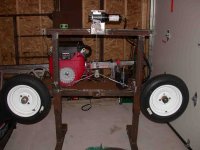
Unbalance would act in the direction that you have tried to compensate for with those wheels you have mounted on the sliding part of the assembly.

But from what I think I see in your photos, there is an even greater opportunity for binding pressure to be felt by the sliding sides of the square tubing, on the platform side [at the bottom] and the other side, opposite the platform side [at the top].

So when you put extra weight on the platform you may be causing a bind, regardless of where you put it. If you want to prove this, put the engine in the middle for a test. If you still get the bind it is not from umballance, but rather from the cantilever effect of the weight of the platform and what is it is carrying.

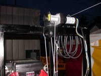
If this is the case, then even pullng upwards with two cables, one at each vertical sliding point, still may not cure the problem. You need enough upward force to overcome the friction of the binding points, which would be as Wharv said, at the top outside, and bottom inside [platform side] of the sliding pieces that the platform is attached to. Your little winch may not have the force to overcome the friction, regardless of how you try to pull upwards.

As others have said, the best solution is to reduce the friction. Even if you don't want to use grease, you might try some just to prove the theory that friction is the problem and to help identify where you need to put compensating rollers or bearings of some type.

You might also try lifting the outside edge of the platform, while the winch is in bind mode, to see if a little lift will cause the platform to unbind. The idea being that a little lift on the outside, would cause pressure to be relieved from the friction point at the top, enabling the winch to do its job. I think, but I'm not certain, that there is a sort of multiplying effect, and that a little lift to unbind something goes a long way toward friction reduction at the bind point.

If all the above seems like nonsense, just forget about it, but do take another look at your assumption that it is the unballance along the platform lenght that is the problem. My gut says it isn't, but like everyone else, we are only looking at pictures... /forums/images/graemlins/smile.gif

Hope I'm not full of hot air here...I think I am seeing what the pictures are showing... /forums/images/graemlins/smile.gif
 
   / Portable Log Mill #27  
Scott

I'm almost afaraid to say this but I have serious questions that the cable lift will ever work to your satisfaction. Have you considered a pair of threaded rods on each side of the carriage which each rotate in a pair of bearing blocks. The portion of the cariage that you are moving has a nut on it and when you turn the rod, the carriage goes up or down depending on which way you rotate. This can apply a lot of very even force and is also very repeatable to set the cuts. Another benefit is that if you ever want to automate it is a simple matter of adding a motor.
If you would like further details I could send you some plans of a mill I have been working on.

Andy
 
   / Portable Log Mill
  • Thread Starter
#28  
Henro, your absolutely correct. When the binding occurs in that one corner I can add a little upward pressure (just lifting it up with my hand) and it goes right up. I am almost tempted to weld a handle in the back where the binding occurs. If that’s what it takes to move this, than so be it.

This weekend I will try to round the top of the 2 ½ in tube stock the best I can. This may help in reducing the friction and binding. The problem is I don't have much room to work with. The only way for me to get the sliding section off is to cut the 2" frame at the top.....which I really don't want to do.

I will try grease but I plan on painting this and don't want to do it until then. It would make for a real mess trying to get that off and could cause paint lifting and adhesion problems. At this point I am almost tempted to try it now. I do plan on getting this sandblasted before the painting phase.

Spiker mentioned a product called UHMW, which I don’t know much about. For what I have read it looks like it would be very slippery and could help with this problem. Is it something I put over the 2” frame?

There is a guy that makes these mills (turner mills) and uses a winch to lift the sliding section. He uses pulleys and it works great. His set up is a little different than mine.

Mrcaptianbob, if you could provide a drawing of what you recommend that would be great.

I have to wait till next weekend to try something new.

Thanks for all your support!!
 
   / Portable Log Mill #29  
Scott,
I second the threaded rod approach if you keep up the frustration level. Attached ( I hope) is one idea. Going back to statics/dynamics class, the top diagram shows the ideal state, and why your modified lift didn't help. You need the net resultant side forces zero'ed out and straight lift if you want all the bind out of the system. By introducing the second cable, you still can bias the lifting to one side. The lower portion is my poor job of one thing you may be able to prototype as an easy test, given the work you have in already. I also thought about MrCaptainBobs approach as well with 2 cables, but with the cable windup on the winch being variable, you can't insure equal travel. So here is one approach. Fix the cable at the top near your outer uprights. Bring them togther at the middle of the bottom with a short piece of chain. Attach your winch cable to the chain, and crank away. If you need to, move left or right a chain link at a time with the attachment point to account for the weight distribution. The only issue here is the amount of total lift you will get out of the system, unless you move the pulley down lower. If you try this, let me know how you make out. A better approach would be to add more pulleys to make the cable runs orthogonal - at 90degree angles only. This makes force reduction alot easier. If the prototype works, this will be better.
By the way,UHMW stands for Ultra High Molecular Weight, it is a high end plastic. You can find it in a lot of woodworking magazines among other places. They use it behind sanders - very slippery, very durable.
 
   / Portable Log Mill #30  
Someday, I'll get this post thing figured out. /forums/images/graemlins/frown.gif /forums/images/graemlins/mad.gif /forums/images/graemlins/crazy.gif /forums/images/graemlins/grin.gif
 

Attachments

  • 391553-Untitled-1.psd.gif
    391553-Untitled-1.psd.gif
    4.4 KB · Views: 321

Tractor & Equipment Auctions

2013 MACK CHU613 (A50854)
2013 MACK CHU613...
BUYERS PREMIUM & PAYMENT TERMS (A51222)
BUYERS PREMIUM &...
2016 John Deere 35G Mini Excavator (A49461)
2016 John Deere...
2014 Brent 1596T Dual Auger Grain Cart (A50657)
2014 Brent 1596T...
2019 Ford F550 4x4 Bucket Truck with Altec AT41 Boom - 46FT Working Height and Jib Winch (A51039)
2019 Ford F550 4x4...
197359 (A50458)
197359 (A50458)
 
Top