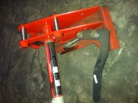
Well, I got one (not one of the $100 kits to review

) in the mail today. It is exactly what I expected, but I have one question and one suggestion. The question is how is the stud supposed to go on the lever? I put it in the way I think it is supposed to go, with the long threaded end in the hole in the plate with a nut to tighten it down to prevent movement, but then no matter how tight I make everything, I get very little spring tension to control the lever arm. I would like more flexibility for adjustment there. In the assembled one I put it together so that it compressed the spring, but now it isn't tight enough to stay with repeated open and close movements. Am I wrong with either approach? How is it supposed to be assembled?
The thing I think could be changed is the actual plate itself. There is no place to weld the cross bar to it. It requires that part to be behind the mechanism. That may not be a huge deal to everyone, but it is an inefficient design as it adds two inches to the thickness of the adapter. It almost has room by the round sleeve that guides the pin, but there is a grease zerk there that will be in the way. I guess a piece of C channel could go there, but it would be nice to be able to use a square tube there instead. It is also a little thin for my use (looks like 3/16", but I didn't measure). I plan on using 1/2" plate. I am going to cut the plate off and weld the sleeve and the post onto my own plate. It would be better for me to have those not welded to this plate, but instead include a template to make welding it to my own plate.
I am not ready to start the build yet, but when I do, I will start a thread in the build it yourself section. Thanks for making this available, I think it is a great value overall and am very excited to start this build.