Repairing sheared impeller shaft - JD 47 snowblower attachment

   / Repairing sheared impeller shaft - JD 47 snowblower attachment
  • Thread Starter
#11  
Thanks to everybody for your inputs on this project, especially Jthibodeau. I'm very happy to report some excellent progress on this.

I don't have any huge aluminum pipe that would match this gear, so some aluminum seats were made, one for each chuck jaw. The gear was set in the 4 jaw chuck with an indicator on the shaft surface and also on the side of the gear. It was dialed in to within .0005". I was happy to see that the shaft was hardened only at the surface. Still it wasn't too hard for an HSS cutter or drill bit to get through it. It was tough on the surface but then cut nicely once through that.
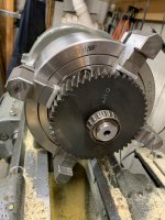
Machining1.jpg

Went through a long series of drill bits to bore out the old shaft, taking off about 1/32" with each bit. Lots of oil.
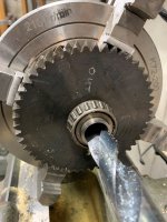
Machining2.jpg

When the shaft was reduced to about .015" remaining, it was time to switch to a carbide boring bar. The squeal from the HSS drill let me know that it was getting into the hard surface.

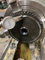
Machining3.jpg

After a few passes with the boring bar, the bearings dropped off. A couple more passes were taken to clean up the radius that was there in the gear/shaft interface (one-piece forged part!!!!). Now the gear has to come out of the chuck so the spacing of the bearings can be measured. A reference surface was turned on the side of the gear so it can be re-aligned perfectly. The side of the gear was originally machined with a very coarse feed, and those mill marks made it hard to be certain that the gear face was perfectly aligned. At least it can now be returned to the alignment used while boring the center hole.
Machining4.jpg

This will lead to a series of questions that I will need help with. I'll put those in the next post.
 
   / Repairing sheared impeller shaft - JD 47 snowblower attachment
  • Thread Starter
#12  
There are some things that I'll need some input from more experienced machinists. I have an electrical engineering degree, so I'm lacking on the mechanical side.

Here's what Jthibodeau posted earlier (very valuable input!!). I have more questions relative to this.
-------------------------------------------------------------------------------------------------------------
"I would not anneal the gear before boring. You need everything straight to indicate it in. Just hard turn with carbide tools. Use pre- hardened 100ksi shaft. 50Rc or so. Original gear may only be induction hardened. Core may be soft.

Do not fully weld. Drill and ream a few (3) equally spaced dowel holes that are centered on the split between the shaft and gear. Press dowels below flush and TIG tack in place. Dress tack welds flush. If fully welded it may warp gear, or crack on HAZ boundary.

Instead of making shaft 2", make it 3/16" smaller diameter than the OD of the inner bearing race. This way the shaft and gear are captured by the bearings and cannot walk apart."
--------------------------------------------------------------------------------------------------------------

My Questions:
1. Shaft material type. 100Ksi. This is new to me. Is McMaster Carr the place to get this, or is there someplace that might be more cost-appealing?
2. Shaft design. I can understand captivating the gear with the inner bearing races. However, I'm thinking that it would be good to machine a flange that runs up the side of the gear on the output side, that would make it possible to drill and tap some screws into the gear to hold it in place while drilling and reaming holes for the pins. This is why I thought starting with 2" material would give me enough of a flange for these screws. "
3. Interference fit between the gear and the shaft. If the gear is bored out to 1.500", for example, what would the mating shaft diameter be? [Edit: I have access to liquid nitrogen, for cooling the shaft when it comes to shrinking it for assembly to the gear.]
4. Press fit between bearings and the shaft. If the ID of the bearing races are 1.000", what would the mating surface of the new shaft be?

Where else can you have such fun?
 
   / Repairing sheared impeller shaft - JD 47 snowblower attachment #13  
First of all I'm not a machinist but am following this with a lot of interest.

I really like the idea of using three dowels instead of welding. The reasoning of it all makes sense to me and I've seen it done before and know it works. The only difference was that the machinist used Allan set screws instead of dowels but the principle is the same. If you tapped the holes and used Allan screws the gear would not move either. For me the advantage would be that I wouldn't need to buy a reamer as I already have taps.

Now here is where I'm going to suggest a totally different idea for fastening the shaft to the gear. If you did some careful machining it looks like you have enough room to use a Browning style taper lock hub to hold the gear onto the shaft. My reasoning for this is that if the shaft should ever break again it would be a lot easier to replace. Now I could be wrong about the room. That is for you to decide. You would either need to shim the shaft between the bearings to get the required bearing spacing or machine the Browning hub for the required clearance.
 
   / Repairing sheared impeller shaft - JD 47 snowblower attachment #14  
If it is pressed together with a heated gear/ cooled shaft, theres no need for a flange with a medium press fit. Shaft is locked once temps equalize. As stated above, you can drill and tap 10-32 at the interface and apply shcs with red loctite. Do not drill through, you want to tighten against the bottom of the hole. Finish the tapping with a bottoming tap. Cut off the body of the bolts and dress flush. The threads will keep the shaft from walking during finish machining of the bearing bores. The bolts are now the dowels for torque. Bolts should be dressed slightly below flush. Again, interface diameter is the midpoint of the inner race face. As you showed, the reference faces are very important for dialing in the gear after pressing in and securing the shaft. Drill the locking bolts/dowels from the short bearing stub side.

Interference fit at gear is .0015~0.0020 with heating/cooling, but have to act fast.

Interference at bearing is 0.000~0.0003. Warm bearing slightly in a toaster oven to install. 250°F should be enough.
 
Last edited:
   / Repairing sheared impeller shaft - JD 47 snowblower attachment #15  
I would use 4340 QT (quenched & tempered) shaft material. About 36Rc and 130ksi tensile, 100ksi yield. It is fatigue resistant and commonly used for axles and crankshafts. May find online at Metals Supermarket. You only need about a foot, right?
 
Last edited:
   / Repairing sheared impeller shaft - JD 47 snowblower attachment #16  
Search 4340 bar on ebay. Mwilliams axles is selling drops for $2.50/lb. Converts to $23.70/ft. They can heat treat for a flat $60. You would need to discuss their hardness and temper. Most bearing races are ground. Do you have a tool post grinder?
 
   / Repairing sheared impeller shaft - JD 47 snowblower attachment
  • Thread Starter
#17  
My local steel supplier had 4140 annealed and heat treated in stock. I bought some of each. I'll see how the 4140 HT machines, hopefully I can work with that. The rep at the supplier said that he sells the HT 2:1 over the annealed and people have no issues with machining it. I ordered it before I saw the recommendation for 4340. I'm willing to bet that the 4140 HT will be stronger than the original forged steel JD used.

Once I get the steel stock, I'll do some experimenting with machining some test parts and confirming the intended interference fit between the shaft and the gear. I'll assemble test parts with pins and then see if I can beat them apart.

What is the advantage of using a TP grinder for the bearing surfaces?

I bought a tool post grinder when I got my lathe, but have never used it. More experimenting!
 
   / Repairing sheared impeller shaft - JD 47 snowblower attachment #18  
4140 HT is typically 28-32 RC and 100ksi. It is not as fatigue resistant as 4340 which was developed for shafting. The 4140 should work okay. If it breaks again, you can redo from 4340.

The TP grinder is the best way to get an exact fit and ensure that the shaft is round. Especially if you are heat treating a shaft to 200ksi. You rough machine to .002 oversize or so, HT, and finish grind 0.0005~0.0001 at a pass.

You can also finish grind the ID of the gear. It is often difficult to cut less than 0.001" , but no such problem with a TP grinder. Glad to hear you have one.
 
Last edited:
   / Repairing sheared impeller shaft - JD 47 snowblower attachment
  • Thread Starter
#19  
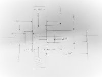
Put together a drawing of this assembly. The bearing is a Timken L44643 with an ID of 1.0000". From what I'm reading on the Timken site, it looks like I would machine the mating shaft surface to 1.0000-.9995. Does that make sense?

Shaft Drawing2.jpg

The thought of assembling the gear to the shaft, heating the gear and freezing the shaft, is a bit terrifying to me. If everything is done right, then once the temps stabilize, the two parts would be impossible to separate. So that flange is there on the output side of the gear so the gear can be slipped onto the shaft and alignment should be established. Without that flange, how would I establish the alignment quickly before everything locks into place?
 
   / Repairing sheared impeller shaft - JD 47 snowblower attachment #20  
Put together a drawing of this assembly. The bearing is a Timken L44643 with an ID of 1.0000". From what I'm reading on the Timken site, it looks like I would machine the mating shaft surface to 1.0000-.9995. Does that make sense?

View attachment 681394

The thought of assembling the gear to the shaft, heating the gear and freezing the shaft, is a bit terrifying to me. If everything is done right, then once the temps stabilize, the two parts would be impossible to separate. So that flange is there on the output side of the gear so the gear can be slipped onto the shaft and alignment should be established. Without that flange, how would I establish the alignment quickly before everything locks into place?

Well you do have a flange in your drawing....

Just get it close and before temperatures equalize just use a brass hammer to make slight adjustments. You'll have enough time before you can't move anything at all. Especially with the size of the gear. I've heated flywheel ring gears and slid them onto the flywheel. If the flywheel is outside in -20 degree weather and the ring gear comes out of the oven @ 250 degrees and goes outside to slide onto the flywheel it still slips on quite easily.

I'm sure someone else will have an even better idea...
 

Tractor & Equipment Auctions

2013 Ford Explorer SUV (A44572)
2013 Ford Explorer...
2017 Ford Explorer AWD SUV (A44572)
2017 Ford Explorer...
INOP Skid Steer Backhoe Attachment (A44391)
INOP Skid Steer...
2014 Kubota M6060 Tractor (A44391)
2014 Kubota M6060...
Heavy-Duty 4-Wheel Rolling Warehouse Cart  74in x 32in (A46877)
Heavy-Duty 4-Wheel...
2003 TRAILMOBILE 32FT DRY VAN (A43004)
2003 TRAILMOBILE...
 
Top