Cedar Pete
New member
- Joined
- Jan 6, 2024
- Messages
- 5
- Tractor
- JD 5065E
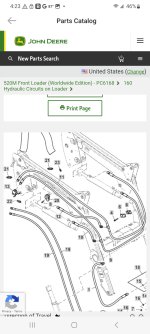
Hey Folks! Hoping somebody has a shared experience and can advise. I blew a hydraulic hose for FEL lift (extend, marked blue) near the big hose valve at the tractor interconnect. I've looked at JD diagrams and discovered a few things.
They run their lines inside the steel arm tubes to the front of the FEL. It appears that i need to access that somehow or otherwise break a line connection that appears to be inside that rectangular tube. Does anybody know the magic trick to do this? Maybe disconnect the short connecting hose 14 at the cylinder, and pulling it out with hose 13? Don't I need to pull a line of some sort thru as I remove the hose, so i can pull the new hose thru?
The drawing shows the right side blue extend (line with the valve) having an inline T port that attaches a short connecting hose 14 to the FWD end of the main right arm cylinder. A red connector is on the REAR of the right cylinder. Their dwg then shows the blue line crossing to the left and connecting to the left main arm cylinder, to the REAR port. My tractor actually has a red hose marking on that port, and a blue marking on the FWD port. I can't see or disassemble the hose if I don't know which end to break and connections are inside this arm. I think the hose part 13 is drawn incorrectly, and should be shown connected to the FWD left arm main cylinder port. What do you think?
Thanks in advance!