Show What Tool You Made*

   / Show What Tool You Made*
  • Thread Starter
#21  
Here's another tool photo I just dug out. It's a pipe notcher I built.

Just make another and send it to me. FedEx overnight.

Seriously, that thing is great.
 
   / Show What Tool You Made* #22  
Wow .. That reloading press is great !

Here's my oil change tool. A socket extension to reach the drain plug on a low slung car without lifting it. Made with 1/2 pipe welded between an extension cut into two pieces.

extension.JPG
 
   / Show What Tool You Made*
  • Thread Starter
#23  
I see you bolted it to the floor. I was wondering how you were going to stabilize it. Great job.

I made 2 pedestals using old JD flywheels as bases. I did not want to ruin the flywheels with welds, so I bolted the pedestals to the flywheels. They are really heavy and very stable, but probably not for a vise.

GrinderPedistal1.jpg GrinderPedistal2.jpg CLICK TO ENLARGE

HoseRollerPed1.jpg HoseRollerPed2.jpg
The hose roller is made to either mount on this pedestal or quickly mount it on the wall of a race car's support truck.
 
   / Show What Tool You Made* #24  
Thanks murph. I guess it will take a while for anyone to post anything else, but just to generate some interest in this thread, I will show this 12 volt electro magnet I made about 20 years ago to magnaflux engine heads for cracks. I got the laminated steel plates at a salvage yard. I think they were from a microwave oven transformer. I got the insulated wire from a motor rewind shop, along with some useful information on how to make it. I had to make a special tool to turn the laminate so I could wind the wire on evenly and not harm the wire's insulation (it's like a coating of varnish or paint). After I finished it, I took it back to the motor shop and they dipped it in that insulation for protection.

The magnet is so strong that 2 people cannot pull it off a sheet of steel. In the photos, I put a drink can for size comparison. That loop on top is just a rope handle to carry it.

View attachment 306353 View attachment 306354

View attachment 306355 View attachment 306356


To use it, sprinkle some iron filings on the area you suspect as cracked; then set the magnet on the surface and turn it on. The filings will move to show where the crack is.

Nice. Not sure if you are aware or not but when you check for cracks you need to check twice. The second time the magnet should be 90 degrees to how you had it set the first time. Magnetic particle testing can only detect cracks going perpendicular to the poles of the magnetic.
 
   / Show What Tool You Made* #25  
Nice. Not sure if you are aware or not but when you check for cracks you need to check twice. The second time the magnet should be 90 degrees to how you had it set the first time.
Magnetic particle testing can only detect cracks going perpendicular to the poles of the magnetic.

Not sure I understand the logic behind that. Don't the lines of force follow an arc from 1 pole to the other. So the only time you would miss it is if the crack was very short and directly parallel to the magnet, centered between the poles but fairly far away? Ah the weaker the magnet the more likely that would be a problem too. His seems to be a very strong magnet.
 
   / Show What Tool You Made* #27  
made a horizontal shaper to make panel cabinet doors, it holds three shaper cutters and does the milling on the stiles and rails and panels,
one can mill out a door in about 2 to 3 Min's, if all parts are cut,

I think the best thing about it is relative safe one would all most have to try to get one hand or fingers in it, and a standard shaper is not that safe,

I really like your shaper, does it cut the depth of the cut completely in one pass or is there a way to adjust it until you get the full cut you need? If it is adjustable what and how are the adjustments made? Does each cutter have it's own spindle or does it have a solid shaft that runs through all the bits at the same time, and if it is solid how do you add each cutter and tighten them up to hold them in place? I have a woodmaster planer and also a woodmaster drum sander, and there is a slight resemblance of the bones of a woodmaster planer in the shaper. I commend you on a neat setup.
 
   / Show What Tool You Made* #28  
First it has been many years ago since I made it so this is close,

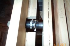
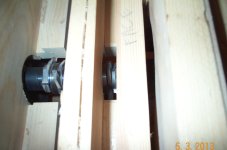
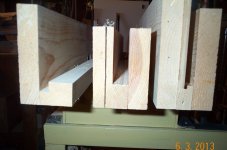
All the cutters have a bearing guide on the depth of cut,

It is one shaft, I think there is a shoulder on the shaft 1 shaft turned down to 3/4" and threaded on the end, is my guessing with out going out and measuring,

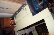
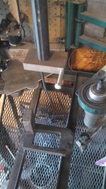
The cutters are stacked on using a number of spacers, and the non pulley bearing is clamped in as well, with a nut, and the other end is just locked in with the eccentric locking collar, locking the eccentric collar down after the nut was tight,,

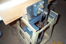
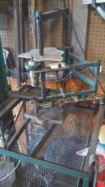
The frame is (need to go look again, I will edit the post when I look later to day) the sides are 1/8" x 6" spaced with a angle iron, looked like 1 1/2" and the ends I think were 4 flat

the legs are angle iron,


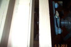
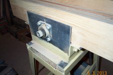
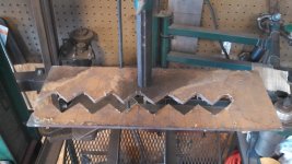
The fences are wood on each end of the box that holds the shaft are two angle irons, top lip slotted the long way, other lip slotted vertical so the fences can be aligned to the cutters, all of the fences have a floor in them, that the product slides on that is nearly in line with the rub bearings, if one wanted perfection one would have to shim the ends of my fences, (one could make three short angles for individual alignment, I think I used Reversible Stile & Rail from Grizzly, C2314 Reversible Stile & Rail - Roman Ogee w/ Rub Collar, 3/4" Bore


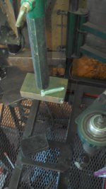
On the end cut there is a sled with a clamp, that rides on the fence, and part of the trick is to have a back up (which is attached to the sled holder) so the ends do not split out,

I have set it up once and have not, changed the setting or the cutters,

personally I think if I really wanted a different profile I would make a new machine, or if I wanted more panel cutters, may be make one with all panel cutters, in it,

(now the RBI panel master claims to be able to run arched doors) my fences do not have that kind of adjustment and would think one would need a shaft for a starting guide on the cutter), when I have made arched doors I will set up the arch cuts on my shaper, really I do not think if I was rebuild or make a different machine that using end pieces that were lower one could make arched on the machine with a different guide fence,

If you have more questions, post and I will check back pm me if I do not respond I may have missed it,

I added pictures to show more of the constuction and the cutters and the rub bearings, hope this helps,
 

Attachments

  • DCP_4211.JPG
    DCP_4211.JPG
    246.3 KB · Views: 888
  • DCP_4212.JPG
    DCP_4212.JPG
    197.1 KB · Views: 611
  • DCP_4213.JPG
    DCP_4213.JPG
    184.8 KB · Views: 574
  • DCP_4202.JPG
    DCP_4202.JPG
    428.9 KB · Views: 869
  • DCP_4203.JPG
    DCP_4203.JPG
    394.7 KB · Views: 614
  • DCP_4204.JPG
    DCP_4204.JPG
    328.5 KB · Views: 619
  • DCP_4209.JPG
    DCP_4209.JPG
    312.9 KB · Views: 698
Last edited:
   / Show What Tool You Made*
  • Thread Starter
#29  
Nice. Not sure if you are aware or not but when you check for cracks you need to check twice. The second time the magnet should be 90 degrees to how you had it set the first time. Magnetic particle testing can only detect cracks going perpendicular to the poles of the magnetic.

I am sure you are correct, but I had never thought of it. Thanks
 
   / Show What Tool You Made* #30  
Here is a pantograph I built that gets a lot of use. Uses a regular hand torch the section of piano hinge to press the cut lever. Plexiglas is great if you only have a few parts because it is so easy to make a template or they can be made from steel so the magnet guides the torch around. The torch mounts unbolt and you can clamp a plasma in for other materials. Makes for easy cutting and faster to setup than the CNC table for just a few parts.

The speed control is a dash light dimmer out of an'86 RX7. The laminated paper next to it is a pressure/nozzle chart for the torch.
 

Attachments

  • IMG_20130306_163953_915.jpg
    IMG_20130306_163953_915.jpg
    499.9 KB · Views: 7,717
  • IMG_20130306_164243_854.jpg
    IMG_20130306_164243_854.jpg
    459.4 KB · Views: 2,733
  • IMG_20130306_164344_072.jpg
    IMG_20130306_164344_072.jpg
    299.6 KB · Views: 1,888
  • IMG_20130306_164556_347.jpg
    IMG_20130306_164556_347.jpg
    344.3 KB · Views: 2,994
 
Top