Snowblower plans?

   / Snowblower plans?
  • Thread Starter
#41  
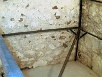
Here is one angle iron stiffener. There will be four of these, one on each end, two spaced out along the middle length of the housing. The two on the ends also serve as convenient faces to bolt through to hold on the end cap plates. The four of these stiffeners are built identical, and that is also what keeps the housing in shape across its width.
 

Attachments

  • 546077-PC120053.JPG
    546077-PC120053.JPG
    41.1 KB · Views: 2,006
   / Snowblower plans?
  • Thread Starter
#42  
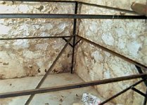
Here's one being clamped on. It will be welded in place.
 

Attachments

  • 546079-PC120058.JPG
    546079-PC120058.JPG
    53 KB · Views: 1,717
   / Snowblower plans?
  • Thread Starter
#43  
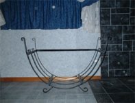
Finally for today, here is a view from the side. You can see the end cap plate in the foreground, and the housing stretching away from you toward the right. So far, so good.
 

Attachments

  • 546090-PC120059.JPG
    546090-PC120059.JPG
    35.5 KB · Views: 2,033
   / Snowblower plans? #44  
</font><font color="blue" class="small">( Here is one angle iron stiffener. .... )</font>

Jim, did you roll these yourself? What type of machine was required to form them?

Thanks in advance, Andrew

PS. The blower looks like quite a project!
 
   / Snowblower plans?
  • Thread Starter
#45  
No, I didnt roll them, they were rolled by some kind of special pupose machine. I found about ten of them in the industrial junkyard near my house. They had an 18 inch diameter when I found them. I had to modify them to 15.3" diameter. To do so, I drilled thru the ends so I could stretch a pc of threaded rod across the ends, then tightned it down a bit, and hit the free leg on the anvil to stretch it. Then tighten, then hit to stretch again. 20 minutes of cold working with the flat of the 2 pounder made them look pretty nice, comparing to a pencil line on paper. I finished a second one last nite, two more to go. I will be glad when that step is done.
 
   / Snowblower plans? #46  
Very interesting. I'm in the planning stages of a similar project and your project has given me some good ideas, Thanks. My intent is to fabricate a truck mountable snowblower similar to Hanson's product. I'll be watching your progress and can't wait to see the finished product, providing there isn't another two year hiatus. I have those myself, I started my blower idea in the late seventies and am just getting around to building it.
DTS
 
   / Snowblower plans?
  • Thread Starter
#47  
There will be NO more delays, this darn thing will blow snow this season.
 
   / Snowblower plans? #48  
In your design, I see that you are making a single stage blower. What rpm do you plan on turning that assembly and how far do you figure the snow will fly?
Thanks,
DTS
 
   / Snowblower plans? #49  
Sorry for the RPM question, (1000) the first time I read this thread was last night and I spent most of my time figuring out how to post and forgot that you mentioned it in the earlier posts. But I am interested in how you derived that figure and the distance you figure the snow will go.
Thanks,
DTS
 
   / Snowblower plans?
  • Thread Starter
#50  
Impeller speed? Here is my reasoning: There is a guy on this forum who beleives that 5000 feet per minute (FPM) tip velocity is needed to really throw snow. My old blower on the front of my Honda rider ran at 3000 and worked pretty well. It would throw the snow about 25 feet, more or less depending on the snow moisture (wet snow threw pretty well, dry snow didnt seem to go as far). So, I used these two data points as bounds. Next, since this attachment goes on a diesel tractor, the torque is available across a wider rpm range, so the attachment can be run at part-throttle if normal PTO speed seems excessive due to vibration of the impeller or something.
With 15 inch diameter, it has a circumference of 47 inches, times 1000 rpm, divided by 12 inches to the foot, gives a tip velocity of 4000 FPM at full PTO rpm speed. Its a good starting guess, and can be changed with gearing change. As I get further along next week, I will be able to show a photo of the drive train. There is a right angle gearbox, a line shaft, and a final chain speed reduction drive on the side. The chain speed reduction is a 2:1 reduction, 'cause the tractor output on the front runs 2000. It will be easy to put a smaller or larger driven sprocket on to increase or decrease the speed, if needed after testing. More to come...
 

Tractor & Equipment Auctions

2021 Dosko 337S-13HC Walk-Behind Stump Grinder (A49461)
2021 Dosko...
2016 Ford Fusion Sedan (A50324)
2016 Ford Fusion...
2015 FORD F-250XL SUPER DUTY SERVICE TRUCK (A51406)
2015 FORD F-250XL...
2016 FREIGHTLINER M2 DAY CAB (A51222)
2016 FREIGHTLINER...
2015 John Deere 35G Mini Excavator (A49461)
2015 John Deere...
2015 International DuraStar 4300 Street Sweeper Truck (A50323)
2015 International...
 
Top