groundcover
Elite Member
Worth dropping a new engine into it ?
Hopefully that's the extent of it.
Since Piston hit the head and valve are you sure the crank or connecting rod are not damaged. Like you stated a whole lot of inertia to shear that flywheel key and drive that valve stem through the head, break piston skirt, etc.
Worth dropping a new engine into it ?
Thank you oldnslo! I'll need it!Pt
Wishing you the best on getting than tractor operational again.
Is he going to Magnaflux the head to look for cracks?Thank you oldnslo! I'll need it!
I did left the head at the engine repair shop today. Interestingly enough, the guy was more worried about the hole that the valve stem poked through the head than the damage on the valve seats. He says he can handle the seats no problem.
We didn't go that far yet. Basically he was still going to see if he could fix the head. Maybe he will give me an update later in the week.Is he going to Magnaflux the head to look for cracks?
I'm thinking that's a possibility with the piston hitting the head -especially considering the fractures on the piston skirt
")
Thank for the ideas and the sketch. All valid concerns indeed.Nice work!
On the oil filter adapter insert it appears from the pic that you machined a smaller diameter thin ring that press fit on the OD to the ID of the cast ring boss. There is an overhang of the insert over the cast oil passages. I'm trying to understand how that is going to seal correctly and not have a seeping leak, especially when there's a possibility of that thin ring flexing from over tightening the filter with that overhang? Did you use a boring head or rotary table to cut a flat base on the casting to create a flat surface for that insert to seat up against?
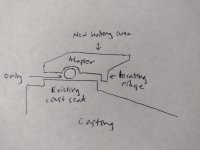
Here is an idea using an o-ring to make an adapter that avoids that potential issue. It would space the filter out a bit and may or may not require a longer threaded insert depending on thicknesses involved. This style adapter would also avoid any overhang obstruction of those oil passages although it's likely not that significant. Here is a sketched cross-section of what I have in mind:
Yes I think I follow. I like the groove idea to provide space for the locktite. What I wasn't clear on is if you machined a surface in the oil passage portion of the casting parallel to the filter seat for the insert to seat up against and provide for axial loading or if the insert is only being held suspended by the press fit OD?Thank for the ideas and the sketch. All valid concerns indeed.
I only had about 3 to 3.5 mm (about 1/8") of thickness to work with. The o-ring idea is great, but didn't have much room to work with. I could also have cut the o-ring groove on the filter housing instead of on the ring.
I machined a mandrel with the M16x1.5 thread and did it so it would stick about 2" from the chuck and threaded the filter housing on it. This allowed be to use a boring bar to machine the inner diameter of the factory sealing ring to true up all the surfaces.
Then I machined the new ring, to press fit on the filter housing. On this ring, I machined a tiny groove on the outside diameter, just with the tip of the toolbit, then used Loctite 603 and pressed it into place. This idea was that it would provide a groove for the glue to sit and hopefully provide a good seal all around it.
Finally, I put the mandrel back on the lathe, and machined both surfaces flat. Also, on the ring, I machined a taper inside so it would give more clearance on that hole in the filter housing. Not entirely necessary but just an extra step to make sure. The angle of the photo above doesn't help and makes it look like it covers a lot of the hole but it really doesn't.
I think it will work fine but won't be surprised if it tries to leak on me.
One issue I didn't realize before is that the OD of the new filter bottoms out on the original sealing surface. While the seal of the filter sits proud about 2 to 3 mm, I'm a little concerned it may try to leak there. I may sill go ahead and turn the outside diameter of the original sealing surface down a little bit.
I hope I explained this in an understandable way.
I did machine the surface as you said, so the ring bottoms out on a machined surface on the filter housing.Yes I think I follow. I like the groove idea to provide space for the locktite. What I wasn't clear on is if you machined a surface in the oil passage portion of the casting parallel to the filter seat for the insert to seat up against and provide for axial loading or if the insert is only being held suspended by the press fit OD?
Hopefully it will hold with the additional filter edge clearance cut as you mentioned. It occurred to me that if it does leak sometime down the line that groove for locktite could be replaced with a thin oring around the OD of the insert to allow for some flex.
Nice work and thanks much for sharing!
There are welding rods that can be used to build up that shaft that will be plenty hard enough. But then you would need to grind it to size, also, the size would need to be very exact. One option could be to use a hardened bushing that is a press fit or a shrink fit onto the shaft. Once again the size needs to be controlled exactly. The shaft could be turned to a .00254 interference fit with a couple grooves about 1mm long and .07mm deep. The grooves would be for some Loctite. I think 609 is the right number. If you decide to use a bronze bushing I would suggest aluminum nickel bronze alloy. This alloy excels in high load situations. It will tolerate low lube situations better than many other bearing bronze alloys. It is quite slick. However, if oil starved for relatively long periods it will tend to wear less than the steel shaft running in the bushing.In the last couple of days, I've pulled the rear gearbox out and started going through it. Found 3 bad bearings and seals and found out that it has surprisingly big gears for the PTO. Wasn't expecting that.
Both brakes had one broken shoe that got repaired on each side for some reason. Not sure what would've caused that. At least they were relined at some point, so I just need to clean those out and put it back together.
The shift rails had lots of rust as I said previously but also the plunger was so wore out that it didn't even have a point anymore to sit on the holes of the rails. Also, both springs were rusted and broken. Couple more things to fix.
View attachment 840896 View attachment 840897
Spacer/4WD selector. Has one bad bearing and looks like two bad seals.
View attachment 840898 View attachment 840899
Rear left side brake, axle and final drive:
View attachment 840900 View attachment 840901
View attachment 840902 View attachment 840903
PTO pictures. On this one, a needle bearing gave out and damaged the shaft (2nd) picture. Since the needles ran on the hardened shaft and while I can build the shaft back up, I can't recreate the hardness of it so I may replace this bearing with a bronze bushing instead. Still debating on that.
View attachment 840904 View attachment 840905
One thing I'm liking in this tractor so far is that it pretty much uses just off the shelf parts, like bearings, seals, pins, etc. Nothing proprietary to the manufacturer.
There are welding rods that can be used to build up that shaft that will be plenty hard enough. But then you would need to grind it to size, also, the size would need to be very exact. One option could be to use a hardened bushing that is a press fit or a shrink fit onto the shaft. Once again the size needs to be controlled exactly. The shaft could be turned to a .00254 interference fit with a couple grooves about 1mm long and .07mm deep. The grooves would be for some Loctite. I think 609 is the right number. If you decide to use a bronze bushing I would suggest aluminum nickel bronze alloy. This alloy excels in high load situations. It will tolerate low lube situations better than many other bearing bronze alloys. It is quite slick. However, if oil starved for relatively long periods it will tend to wear less than the steel shaft running in the bushing.
Eric
I've done that die grinder on the tool post trick several times with various rigid adapters and my experience has been that you don't get results like a real tool post grinder because you are limited by the die grinder bearings which tend to be on the loosey-goosey side in the runout department (probably deliberate to deal with grinding dust). I've found it works in some applications that you only need +/- 0.001-0.002" for it to work, but as etpm mentioned above you'll need a very exact fit here and unless you have an exceptional high precision bearing die grinder I'm thinking you're not going to have much luck. Of course YMMVThanks for all those suggestions. I'll see what I can find regarding the welding rods. I could rig a die grinder on the tool post and grind it to size if needed.
As far as oil starvation, that bushing will be under the oil level 100% of the time. That's why my first idea was the bushing. A couple grooves for the oil to flow in and should last a decent amount of time.
The shaft will only spin on the bush in the 540 PTO gear. If I use 750/540E, it's a direct drive on this area and the shaft spins at the same speed of the bushing.
This one is turning out to be quite a basketcase. Not sure if I won on this one. Just about everything I take apart, there is something wrong with it and I still have the front half and steering box to pull apart.You really bought a basketcase but by golly you're making it come together. Kudos to your tenacity and skill set. Looking great and thanks again for sharing