Starting my bridge!!

   / Starting my bridge!! #71  
Just google steel beam deflections and steel beam stress.

You will get all kinds of formulas......distributed loads, point loads, etc.

But all common steel has given properties. All common I-beam shapes, Channel, tube, etc.

Its simply math from that point. The key spec you are looking for to calculate deflection is called moment of inertia (i⁴) You can get some I-beam specs here W-Beams - American Wide Flange Beams

The LIGHTEST 10" I-beam they list is a W10x12. Meaning 10" tall and 12lbs per foot. And has a moment of inertia of 53.8

For simple deflection with a load at mid span.....(WLᶟ)/(48Ei⁴)
In other words......weight times the length in inches cubed.....divided by 48 times modulus of elasticity times i⁴

Modulus of elasticity of steel is 30,000,000

So, with 3000 pounds at the middle of a 22' span:
(3000 x 264 x 264 x 264)/(48 x 30,000,000 x 53.8) = 0.712" of deflection.

You should try and keep deflection under L/360. So 264"/360 = 0.733 So a pair of those beams in theory is good to a little more than 6000# total at midspan with a point load.

But with steel members that arent common.......or listed anywhere.....for example if your trailers I-beams arent actually I-beams but rather plates of steel welded together.....or in the OP's case of maybe stiffening tubing with cable or strap or re-bar.....makes it VERY complicated to calculate the moment of inertia. And therefore very difficult to assign a proper load value. Because alot more things come into play other than just raw steel. For example.....quality of the welds, enough weld contact area, bracing, etc.

A fun little tool/calculator I downloaded years ago so I dont know if its still avalialbe is called BeamBoy. It calculates all the stress and deflection for a given shape. And they have alot of shapes already stored in the program with the relevant parameters.

So in the above example of the 22' span and W10x12 beam it looks like this:
View attachment 788655
View attachment 788656
Brings me back to my college days, statics and dynamics class.
So glad this is all in books/online for lookup now.
The formulas always gave me headaches deriving them.
 
   / Starting my bridge!! #72  
Just google steel beam deflections and steel beam stress.

You will get all kinds of formulas......distributed loads, point loads, etc.

But all common steel has given properties. All common I-beam shapes, Channel, tube, etc.

Its simply math from that point. The key spec you are looking for to calculate deflection is called moment of inertia (i⁴) You can get some I-beam specs here W-Beams - American Wide Flange Beams

The LIGHTEST 10" I-beam they list is a W10x12. Meaning 10" tall and 12lbs per foot. And has a moment of inertia of 53.8

For simple deflection with a load at mid span.....(WLᶟ)/(48Ei⁴)
In other words......weight times the length in inches cubed.....divided by 48 times modulus of elasticity times i⁴

Modulus of elasticity of steel is 30,000,000

So, with 3000 pounds at the middle of a 22' span:
(3000 x 264 x 264 x 264)/(48 x 30,000,000 x 53.8) = 0.712" of deflection.

You should try and keep deflection under L/360. So 264"/360 = 0.733 So a pair of those beams in theory is good to a little more than 6000# total at midspan with a point load.

But with steel members that arent common.......or listed anywhere.....for example if your trailers I-beams arent actually I-beams but rather plates of steel welded together.....or in the OP's case of maybe stiffening tubing with cable or strap or re-bar.....makes it VERY complicated to calculate the moment of inertia. And therefore very difficult to assign a proper load value. Because alot more things come into play other than just raw steel. For example.....quality of the welds, enough weld contact area, bracing, etc.

A fun little tool/calculator I downloaded years ago so I dont know if its still avalialbe is called BeamBoy. It calculates all the stress and deflection for a given shape. And they have alot of shapes already stored in the program with the relevant parameters.

So in the above example of the 22' span and W10x12 beam it looks like this:
View attachment 788655
View attachment 788656
Thank you, wow, loads of info on that reply. I love math :) but some of this might be beyond me at the moment, thats how a person learns. To me, reading your reply, its apparent that even with deflection and load capacity, it all depends on how good and strong the ends are supported on the beams and where it would be necessary to have like a frost foundation (footing wide enough to keep things stable) and support wall at each end because the load (weight) can shift and put more weight on one side or in front or back etc. Another poster just mentioned why not use a culvert, of course a culvert would have to be sized correctly and then lots of fill built up around and over it. many things to think of, but safety should be the first consideration and without proper design, safety might not be there. interesting for sure.
 
   / Starting my bridge!! #73  
Great Project! Hope you keep posting pics/progress.

Good luck!
 
   / Starting my bridge!! #74  
Interesting build, enjoyed following this! Small streams have a habit of becoming much larger streams during a downpour. Be careful of putting stiffening structures under your bridge as they can serve to catch debris under high water conditions. Have you checked a FEMA flood map for your location? They are based on watershed area and topography plus assumptions on a 100-year rain event. If your bridges abutments are within the 100-year inundation area then water will get up to your bridge.
We have a creek in our front yard which I have long wanted to build a bridge over. When the power company upgraded the lines through our property I was given around 16 power poles, with the thought being to use some in a bridge. Then in 2021 we had two 100-year rain events and I saw the raging torrent our little creek could become, a bridge would would need to be 5’ or so above the bank, which makes this a major project with long approaches. Currently thinking about a draw bridge, using an aluminum bridge kit I found on line.
 
   / Starting my bridge!! #75  
Thank you, wow, loads of info on that reply. I love math :) but some of this might be beyond me at the moment, thats how a person learns. To me, reading your reply, its apparent that even with deflection and load capacity, it all depends on how good and strong the ends are supported on the beams and where it would be necessary to have like a frost foundation (footing wide enough to keep things stable) and support wall at each end because the load (weight) can shift and put more weight on one side or in front or back etc. Another poster just mentioned why not use a culvert, of course a culvert would have to be sized correctly and then lots of fill built up around and over it. many things to think of, but safety should be the first consideration and without proper design, safety might not be there. interesting for sure.
Yes, you have to look at the big picture and the structure as a whole. Cause even with properly sized beams a structure can fail if improperly supported and braced.

BUT......it all starts at the beams. Start with beams that are too small for the load.....and it dont matter how its braced or if you have hoover dams for supports on each end.....the beams will still fail.
 
   / Starting my bridge!! #76  
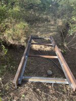
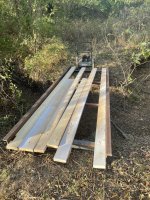
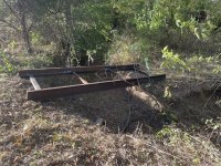
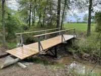
In my barn thread I mentioned a bridge build and people wanted me to post when I was building it.

Todays the day!!!

Approx 20’ span
Approx 7-8’ wide
2x6 tubes for the stringers
A center 2x6 tube under the stringers
3x3 tubes for cross members

6x6 treated timbers for the “foundations” on each end.

End goal is to drive a vehicle across!

View attachment 786740View attachment 786742View attachment 786743View attachment 786745
Depending on the cost of course, but a Sea Can works good as a covered bridge as well. You just pour a cement footing on both sides for it to sit on. The only problem with the sea can is the width. Cars and pickups are good but flatbeds and trailers are quite often too wide.

Thank you for sharing, free steel is always good.

Are you capping the hollow steel or rust proofing the inside?
In my barn thread I mentioned a bridge build and people wanted me to post when I was building it.

Todays the day!!!

Approx 20’ span
Approx 7-8’ wide
2x6 tubes for the stringers
A center 2x6 tube under the stringers
3x3 tubes for cross members

6x6 treated timbers for the “foundations” on each end.

End goal is to drive a vehicle across!

View attachment 786740View attachment 786742View attachment 786743View attachment 786745
 
   / Starting my bridge!! #77  
With free steel, maybe add a couple more 20ft stringers to increase the section modulus out in the middle. “Overbuilt” is in your favor.

I may have missed it but never saw the wall thickness of that 2x6 tube. You might post it, or PM it to one of your engineer-members.

Or add the doublers above deck, like 6” high “wheel railings”.
They don’t have to bear out on the foundation, they do their job “out in the middle”. A 12” high section will increase the strength substantially.

The rounded tube corners will allow welding not totally overhead (for the 12” section suggestion). Maybe you can get help with any overhead welds, or just don’t post pics. Your other welds suggest that you can do it well, or can learn.

Consider padlocking a “post” in the middle it so you have *full control* that only ATVs can cross it if you’re not there.

Your deflection testing/measurement method with the string is good.
Write down the deflections/weight, in the future you can use the string method as a scale to weigh eqpt that crosses your bridge🤓.

Sorry if this sounds “critical”, but F150 kinda gives me the willies. I wouldn’t drive 7,000 lbs over that before a real confident deflection test. My gut suggests verification with 10,000 lbs (about 3x safety factor) right in the middle - would be good to allow one 3500lb F150 axle out in the center.

With testing comes confidence.

Whats the tractor weight?
 
   / Starting my bridge!! #78  
 
   / Starting my bridge!!
  • Thread Starter
#79  
With free steel, maybe add a couple more 20ft stringers to increase the section modulus out in the middle. “Overbuilt” is in your favor.

I may have missed it but never saw the wall thickness of that 2x6 tube. You might post it, or PM it to one of your engineer-members.

Or add the doublers above deck, like 6” high “wheel railings”.
They don’t have to bear out on the foundation, they do their job “out in the middle”. A 12” high section will increase the strength substantially.

The rounded tube corners will allow welding not totally overhead (for the 12” section suggestion). Maybe you can get help with any overhead welds, or just don’t post pics. Your other welds suggest that you can do it well, or can learn.

Consider padlocking a “post” in the middle it so you have *full control* that only ATVs can cross it if you’re not there.

Your deflection testing/measurement method with the string is good.
Write down the deflections/weight, in the future you can use the string method as a scale to weigh eqpt that crosses your bridge🤓.

Sorry if this sounds “critical”, but F150 kinda gives me the willies. I wouldn’t drive 7,000 lbs over that before a real confident deflection test. My gut suggests verification with 10,000 lbs (about 3x safety factor) right in the middle - would be good to allow one 3500lb F150 axle out in the center.

With testing comes confidence.

Whats the tractor weight?
2x6 tubes are 1/8” wall.
Outside tubes have a piece of 3x3x3/16 -20’ welded to them for the 3x3 cross tubes to sit on

There’s another 2x6 tube in the center under the 3x3 tubes

Tractor weighs approx 4000 pounds

E068909C-1861-44E2-AAA6-530B8B903BF8.jpeg

I’m going to build this under each of the stringers out of 5/8 rebar. An Engineer “assisted” me with working out the idea.


I’ll probably also build 2’ or 3’ tall truss style railing on the outboard stringers.

Just about got the ok from the finance manager (wife) for some concrete to lock down both ends of the bridge. She hasn’t actually seen it in person yet!

I like to build stuff!
This is my 4th bridge on property.


A small 12’ long to walk across
B6216C85-AFFF-45D7-AA88-8763EF470895.jpeg644CFA80-5FCA-47B9-A59D-DC8C97264ACD.jpegF0B2BE2F-A5AA-4718-B8A0-E3F52293CC96.jpeg

A 3’ wide 25’ long to walk across
C80E5031-0518-4656-A080-E24BE0E1AEE9.jpeg


The first one I built
5’ wide 25’ long
Post in the center of the creek
ATV/foot traffic only

F2278FCE-31E9-45B0-B160-6028C34A47C5.jpeg
 
   / Starting my bridge!! #80  
Looks like a fun project and lots of work put into it. I agree with the others about not having the substructure for a pickup-sounds like you are trying to remedy that. The footings/abutments are your biggest failure points. Using native soil is always sketchy due to sinking and erosion. Rock is king and having abutments out of the channel width and/or abutment protection is key. In general the bottom of your bridge should be 3’ above the 100year flood level. Most guys make their bridges too short to cut costs but it will always leads to failures of some sort. Eco blocks make great abutments and they’re about 25$. The other option is have you considered a log stringer bridge? If you have trees on your property or can get some you can make a stout ass bridge. We use them for fully loaded log trucks. Here’s a link https://www.dnr.wa.gov/publications/fphp_ins_temp_bridge_ex_plan.pdf
 

Tractor & Equipment Auctions

2025 Wolverine PT-16-01C 3-Point Quick Hitch (A47484)
2025 Wolverine...
2015 Ford Explorer AWD SUV (A44572)
2015 Ford Explorer...
2020 INTERNATIONAL MV607 26FT NON CDL BOX TRUCK (A43005)
2020 INTERNATIONAL...
2018 Toro Groundsmaster 7200 72in Zero Turn Mower (A44572)
2018 Toro...
2021 Godwin CD150S Dri-Prime S/A Towable Dewatering Pump (A44571)
2021 Godwin CD150S...
2019 FREIGHTLINER CASCADIA DAY CAB (A45676)
2019 FREIGHTLINER...
 
Top