schweizer
Gold Member
Hello friends,
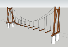
I'm in the design phase of building a suspension bridge (footbridge) across a year-round creek on my land. An earlier bridge got washed away in high water 2 years ago. This one will be higher off the water and stronger. I had designed a wood bridge but now I'm thinking a partial metal design would be better.
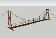
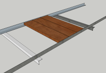
While taking a hike in Yosemite this week, I came across this bridge and I liked some of its design: They used 2-3" angle-iron longitudinally under the horizontal planks, and horizontal angle-iron under that for attachment to the support wires. Pretty simple design and easy to bolt together. Lighter than wood. I would make the end posts taller (12-16') to alleviate some of the sag in the middle. I'm including some pics and my calcs. I'd appreciate any input (especially from any engineers).
First bridge (pardon the wife and in-laws on the bridge):

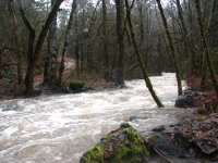
Washed out in high water:
Interesting bridge design in Yosemite:
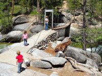
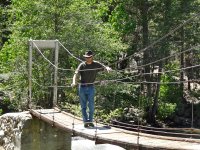
(yes, that's me on the bridge)
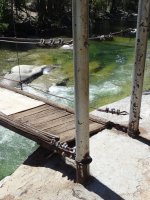
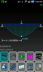
I'm thinking 2 x 2 x 1/8" angle iron would be plenty strong. Here are the calcs:
I = Moment of inertia = 0.19 inch^4 in directions Ix and Iy
E = modulus of elasticity for steel = 30,000,000 psi
Deflection over 4 ft (force at center) of 500 lbs:
= 500 * (48)^3 / (192 * 30,000,000 * 0.19)
= 500 * 110,592 / (192 * 30,000,000 * 0.19)
= 0.0505" or approx 1/16"
Over 2 pieces of angle:
= 0.025" or approx 1/32"
That's seems a very small amount of deflection and would seem to be acceptable?
I'm not quite sure that 0.19 is the correct Moment of inertia. Source:
http://www.engineeringanddesign.com/1/046 Angle Iron Data.xls
The moment of inertia from a different website is 0.9167. Source:
Calculator for Engineers - Moment of Inertia of angle section
(That would give deflection of 0.0104" and 0.0052" respectively, which is even smaller.)
Thanks for any input.
Marcus
I'm in the design phase of building a suspension bridge (footbridge) across a year-round creek on my land. An earlier bridge got washed away in high water 2 years ago. This one will be higher off the water and stronger. I had designed a wood bridge but now I'm thinking a partial metal design would be better.
While taking a hike in Yosemite this week, I came across this bridge and I liked some of its design: They used 2-3" angle-iron longitudinally under the horizontal planks, and horizontal angle-iron under that for attachment to the support wires. Pretty simple design and easy to bolt together. Lighter than wood. I would make the end posts taller (12-16') to alleviate some of the sag in the middle. I'm including some pics and my calcs. I'd appreciate any input (especially from any engineers).
First bridge (pardon the wife and in-laws on the bridge):

Washed out in high water:

Interesting bridge design in Yosemite:


(yes, that's me on the bridge)

I'm thinking 2 x 2 x 1/8" angle iron would be plenty strong. Here are the calcs:
I = Moment of inertia = 0.19 inch^4 in directions Ix and Iy
E = modulus of elasticity for steel = 30,000,000 psi
Deflection over 4 ft (force at center) of 500 lbs:
= 500 * (48)^3 / (192 * 30,000,000 * 0.19)
= 500 * 110,592 / (192 * 30,000,000 * 0.19)
= 0.0505" or approx 1/16"
Over 2 pieces of angle:
= 0.025" or approx 1/32"
That's seems a very small amount of deflection and would seem to be acceptable?
I'm not quite sure that 0.19 is the correct Moment of inertia. Source:
http://www.engineeringanddesign.com/1/046 Angle Iron Data.xls
The moment of inertia from a different website is 0.9167. Source:
Calculator for Engineers - Moment of Inertia of angle section
(That would give deflection of 0.0104" and 0.0052" respectively, which is even smaller.)
Thanks for any input.
Marcus
