Hi Mark
Thanks for the revised reply to my earlier questions.
I have done further testing based on some of the questions you had asked but I guess you changed the post somewhat.
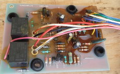
The control PCB is located in a plastic housing under the panel holding the tractor seat.
It has those two large connectors you spoke about and shown on pages 6-25.
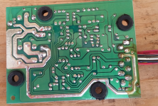
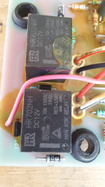
I have attached some photos. This PCB contains two smaller relays, and when you use the up down switch, you can hear them operate.
I tried to do voltage testing, but it lead me to more questions then answers and the voltage is only on most of the system while the motor runs, which is about 2 or 3 seconds so it is near impossible to trace and if you disconnect anything it changes where the voltage is found.
View attachment 563164View attachment 563165View attachment 563163
First for the back up switch, i see that the Red with (L) blue line wire, has a good 12 volts at it, but the Yellow Green line wires, (2 of them) have about 11.5 volts which seems to tell me that they are connected to other voltage sources looking for ground?
I find the wiring diagram lacking good information. On that switch they use the letters S, H and B, but do not transfer that information to the connector.
I find that the push on operation seems to connect the YG and BY wires.
Also i double checked all the switches and when disconnected you can test them for open/close and they all work as they should.
I don't understand the MO3 Blue Yellow line that interconnects all these switches other then they put the voltage to the MO3 pin on the PCB connector pin 11 connector B.
I did follow some of the debugging testing they laid out, and for one item, Connector A of the Back up Controller, it show that Pin 5 should have 12 volts when the key is off and Pin 6 should have voltage when the key is On, however i find power on both pins when key is on. And question why there would be any power back there when the key is off.
I have to wonder how correct this trouble shooting is.
As for wire B that you state goes to the back up relay, this wire must act as the ground for that relay to operate.
I know that I had to pull that relay, as the lights seem to be staying on, but having it removed, should in no way effect the operation for the auto up side of things, which again makes me think that the MO3 BY wire is use to ground out the switch connections.
I still have no idea of where to look for those two diodes, and not sure how they help if that path is to ground.
Right now i am more confused then before.
Looking at the PCB, I cannot see any damage, but since that board is almost impossible to understand, do I just replace it?
Calling it a night, not happy with the three hours spend trouble shooting, as I said, I am more confused now they ever.
Douglas


