Top Link attach hole

   / Top Link attach hole #1  

Bob_Young

Veteran Member
Joined
Jul 5, 2002
Messages
1,244
Location
North of the Fingerlakes - NY
Tractor
Ford 4000; Ford 2000(both 3cyl.);JD40; 2004 Kubota L4300; 2006 Kubota B7610; new 2007 Kubota MX5000
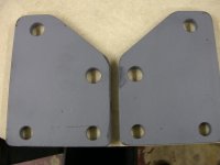
My Kubota L4300 has three holes; top, middle and bottom; where the 3-pt hitch toplink can be attached. I have position control only. The manual has little information on how to choose the proper hole, but there is a table that gives some guidance on tillage attachments. The middle and bottom holes seem to be favored for most everything. The top hole is only recommended for a mouldboard plow operating in 'light soil'.

When using my Woods HBL84-2 rear blade, I've found the toplink is closest to being level when the blade is in operating position when it is attached at the TOP hole. In the middle and bottom holes it's angled up toward the implement sharply (maybe that's the goal).

Anyway, using the top hole gives me more (useful) travel on my hydraulic toplink. In the middle hole, the toplink is nearly fully extended when I have the blade set the way I want. Adding Pat's EZ hitch to the lower lift arms complicated matters by moving everything further back.

What basic principles apply when choosing which hole on the tractor the toplink gets attached to? Does weight of the implement affect this decision? What about the height of the toplink attach point on the implement? Does the top hole have less mechanical advantage than the lower holes or put more stress on the tractor? Of the three, the top hole has the least attaching structure supporting it. Even the manual waffled a bit and said the table guidelines might not apply to all implements.
Bob
 
   / Top Link attach hole #2  
The manual for my L3130 lists 3ph implements and which should be connected to each hole. These guidelines will have been prepared on the basis of using Kubota implements and all of mine are by other manufacturers. Accordingly, my 3ph attachments work best set differently to the recommendations Kubota makes. For example, I like my Buhler rfm and my box blade set in the top hole.

I would guess that Kubota makes different recommendations for your tractor but, for what it's worth, here are the recommendations Kubota makes for mine. These are straight out of the manual.

Moldboard plow - light soil 1 or 2; medium soil 2 or 3; heavy soil 3.
Disc plow - 2 or 3.
Harrow and subsoiler - 2 or 3.
Weeder/ridger - 3.
Earthmover, digger, scraper, manure fork, rear carrier - 3.
Mower - 3 for position control, 4 if draft control.
 
   / Top Link attach hole #3  
Hi Bob,
That's an interesting question and I'd sure like to hear from others who REALLY know the answer.

Anyway, I'll give it a shot...
</font><font color="blue" class="small">( What basic principles apply...)</font>
I saw on your profile that you're and engineer (ret) so you probably got the "basic principles" thing figured out already. The lower holes in relationship, would seem to give more strength and sturdiness if you were to pull or push on that point (not suggesting you do that) because of their location...proximity to the axles and the rest of the hydraulic assembly casing.... more "connected" mass....more resistance to flexing and/or breaking, so to speak.
An example of the principle would be a flagpole solidly anchored in the ground. The farther up the pole you push or pull, the more it would flex or possibly break.

</font><font color="blue" class="small">( Does the top hole have less mechanical advantage than the lower holes or put more stress on the tractor? Does weight of the implement affect this decision? What about the height of the toplink attach point on the implement? )</font>
Taking all that into consideration...
I don't think there is MORE stress so much, but rather how the stress is absorbed better. If the toplink is angled, the load (push or pull) is deflected by a vector force. The greater the angle, more stress is applied to the toplink and its connections. It seems to me that the closer the top link is to level, the better the tractor absorbs the stress. (Assuming the connections are lower, closer to the base of the casting, like the earth securing the flagpole.) And the longer your toplink wil last.

With this in mind, when pulling your blade, resistance to the cutting edge at ground level will force it to pivot on the lower link pins, actually pushing the toplink into the casting, not pulling away from it, especially when going over. hitting a big rock. So it would appear the straighter that link is, the stronger it becomes, and the tractor can absorb that pressure. And because of this, I wouldn't worry so much about which hole to use for pulling your blade, but more for levelness of the toplink.

I also got Pat's EZ Change system and CCM's hydraulic Top & Tilt. When you adjust the tilt, you're basically rotating the implement around the same axis...the lower link pins. So the more leverage you give the TnT, the easier it is on it. I made two 1/2" thick brackets that allows the hydraulic clylinder to have equal travel in both directions and also a little more leverage over the implement. (See Attachment) It put the connection forward by about the same amount the EZ change system pushed it back.
 

Attachments

  • 803440-BOXBLADE BRACKETS.JPG
    803440-BOXBLADE BRACKETS.JPG
    67.2 KB · Views: 471
   / Top Link attach hole #4  
The simple answer is that the lower holes will cause the 3PTH implement to lift higher at the rear when the lower links are raised. The top hole will allow a more level lift. Will it hurt anything if you use the top hole where the lower holes are recommended? I doubt it.
 
   / Top Link attach hole #5  
If you're not using the draft feature it doesn't matter. Just connect to the hole that works best. For heavy tillage work like a bottom plow the draft is used. If you look around that area with the 3 holes I expect you'll see some type of linkage that operates the draft control.
 
   / Top Link attach hole #6  
Charolais may be right about it not making any difference. The holes were actually put there to regulate the amount of force from draft that was put on the mechanical feed back for the draft control. The top hole for light draft and own down to the bottom hole for heavy draft.
 
   / Top Link attach hole #7  
Bob - I chose the center hole for my rear grapple simply because I felt that would best spread the forces exerted on the gearcase over the widest area possible, and possibly reduce any "zipper effect" that might occur if, say, the top 2 bolts were to strip or break, then the middle two, then the bottom 2.

As for: <font color="blue">Does the top hole have less mechanical advantage than the lower holes or put more stress on the tractor? </font> It seems to me that using the top hole would (slightly) reduce the forces placed on the tractor, but then again, I agree with <font color="blue">Of the three, the top hole has the least attaching structure supporting it. </font>

So all in all, I just use the middle hole.
 
   / Top Link attach hole #8  
Good question. I don't know the official answer. What I've done is to experiment and find out which hole works best. The way I look at it, there are so many different attachments from so many different builders that the combination of possibilities is mind boggling, and therefore likely not covered in a list of standard recommendations. Trial and error works for me.

Good luck with it.

Tom
 
   / Top Link attach hole #9  
I keep mine in the center hole at all times for the exact reason Tree Guy stated. It seems to me that the overall mount would hold up better if all the forces and/or stresses were focused on the "center of the mount", putting equal stress on all 6 bolts that connect the top link bracket to the tractor. I have a K L3400 with NO draft control so that is obviously not an issue for me. The only ground-engaging implement I have thus far is a middle buster/sub soiler, and it works just fine in the center hole.
 
   / Top Link attach hole #10  
About the most important consideration is that the top link NEVER be longer than the lift arms. If you work out the geometry, with a too long top link, it'll make the lift arms want to tilt the implement towards the ground. There may be cases where you want this. Perhaps others can comment on this. You CERTAINLY don't want it with a brush hog. This is what happened when they delivered my brush hog. The top link was longer than the lift arms because they didn't mount the bottom pins on the brush hog to their lowest position. The lift would only move the front of the brush hog up about 1", whitch is all that was allowed in taking up the slack in the movable top link position on the brush hog.

Moving the lift pins down on the brush hog fixed the problem.

Ralph
 
   / Top Link attach hole #11  
</font><font color="blue" class="small">( This is what happened when they delivered my brush hog. The top link was longer than the lift arms because they didn't mount the bottom pins on the brush hog to their lowest position. The lift would only move the front of the brush hog up about 1", whitch is all that was allowed in taking up the slack in the movable top link position on the brush hog.

Moving the lift pins down on the brush hog fixed the problem.)</font>

I guess I didn't get this part? Not sure what you mean here.
 
   / Top Link attach hole #12  
Rob, I think I get it, but I'm old, so I can never be too sure. It just seems that if the top link is "too long", it has no "choice" but to "push down" on the attachment as the lift arms rise, thereby tilting the rear of the attachment down. Lowering the pin placement on the attachment effectively "shortens" the top link??? Brain ... hurts .... must ... stop .... thinking ...... John out
 
   / Top Link attach hole #13  
John,
I guess I should've been more clear on my question above. I get the principle but I couldn't figure why his tractor has a top link longer than his lift arms? It should be adjustable enough to become shorter than the lift arms? Mine is...
The other part was repositioning the the lower lift pins on the brushhog, because mine only has one spot for the lower link pins on it.
Just confused ...it's tough to be an idiot, ya know?
 
   / Top Link attach hole #14  
<font color="blue">Just confused ...it's tough to be an idiot, ya know? </font>

Actually, I kind of enjoy it! /forums/images/graemlins/smile.gif
 
   / Top Link attach hole #15  
What...?? Did I read that right...???
You enjoy Me being an idiot...??? /forums/images/graemlins/grin.gif /forums/images/graemlins/grin.gifHA!
Well, you're not the only one. /forums/images/graemlins/grin.gif
 
   / Top Link attach hole
  • Thread Starter
#16  
/forums/images/graemlins/grin.gif It's all relative. I enjoy being an idiot when I think of how much us idiots upset the really intelligent people. We've definitely got 'em outnumbered. /forums/images/graemlins/grin.gif

Anyway, I'm learning alot on this thread. Keep those thoughts coming.

3RRL, many of your thoughts echo my own with one exception. If the toplink were level and the implement, in normal operation, encountered a major obstruction; the toplink would be in compression as the implement tried to pivot forward around the lower lift arm attach points. This would place a forward acting (pushing) force at the tractor attach point while the lower lift arm attach points would be subject to rearward acting (pulling) forces. The implement might not pivot away from the obstacle.

If the toplink were angled up toward the implement the implement could rotate around the top link attach point and tend to lift itself over the obstacle. In so doing the lower lift arms would raise freely to help with this.

If the toplink were angled down toward the implement, I think it would be much like the level toplink case except the implement would definitely not pivot. The hitch mechanism would bind because the lower arms would resist being pushed down.

This talk about pivoting implements over obstructions might not be reality, however. I can remember hooking a 2 bottom moldboard plow on a big tree root once and the only pivoting was when the front of the Ford 4000 pivoted skyward. Come to think of it, the toplink may have been angled down toward the plow on the Ford.

But, as engineers often do, we may be overthinking this. Pick a hole that works and go with it has its appeal. That's pretty much how its' done with Ag tractors. But Ag tractors have beefy behinds compared to CUTs. The rear axle casting of my L4300 looks delicate compared with the Ford 4000.

Thanks to all for the insights.
Bob
 
   / Top Link attach hole #17  
I can tell you how this relates to a ford, with multiple holes in it's toplink rocker. The lowest hole is used for heavy implements, whether ground engaging or not... but specifically ONLY the lower hole for high draft implements.. like blows / box blades / rigid shank cultivators. The upper holes are used for very light draft implements, like spring tooth harrows, as these implements don't have enough draft to activate the draft sensing hyds.. the toplink rocker is a lever.. the higher up you go.. the more mechanical advantage.. thus more stress on the toplink rocker/pump sensing components. The ford manual is very specific about not putting high draft loads int he holes with more mechanical advantage.. as it can damage the valving and linkage that operates the draft control.. etc.

soundguy
 
   / Top Link attach hole #18  
On my LX4, it was not possible to adjust the top link to be shorter than the lift arms at the mowing height (about 3") that I wanted. When the lift pins were moved to their lower positions on the LX4, this kicked the top link attachment point forward, thus shortening the top link length needed.

Ralph
 
   / Top Link attach hole #19  
3RRL

Sorry to change the subject, but how does your top and tilt work with your Pat's Easy change. I am wondering if it will bend any of the parts when I angle my box blade as far as it will angle? /forums/images/graemlins/confused.gif
 
   / Top Link attach hole #20  
Hi Bob,
Just wanted to make a couple of points about my first post on the thread...
</font><font color="blue" class="small">( 3RRL, many of your thoughts echo my own with one exception. If the toplink were level and the implement, in normal operation, encountered a major obstruction; the toplink would be in compression as the implement tried to pivot forward around the lower lift arm attach points. This would place a forward acting (pushing) force at the tractor attach point while the lower lift arm attach points would be subject to rearward acting (pulling) forces. The implement might not pivot away from the obstacle.)</font>
Yes I agree with that principle as I tried in my feeble explanation. /forums/images/graemlins/grin.gif

</font><font color="blue" class="small">( If the toplink were angled up toward the implement the implement could rotate around the top link attach point and tend to lift itself over the obstacle. In so doing the lower lift arms would raise freely to help with this.

If the toplink were angled down toward the implement, I think it would be much like the level toplink case except the implement would definitely not pivot. The hitch mechanism would bind because the lower arms would resist being pushed down.)</font>
Well, at this point I would say the top link is a rigid brace and regardless of it's angle, it would not allow the implement to pivot, as you mentioned about the tractor front raising up.
</font><font color="blue" class="small">( I can remember hooking a 2 bottom moldboard plow on a big tree root once and the only pivoting was when the front of the Ford 4000 pivoted skyward. Come to think of it, the toplink may have been angled down toward the plow on the Ford.)</font>

In my first response I wanted to point out that on a boxblade the force to the blade causes a rearward pulling of the implement thereby making it WANT to pivot around the lower link pins, not that it actually does. The only way to really make the implement pivot on the lower link pins is to have swivel brackets such as used on a brushhog to keep the implement wheel in contact with the ground. Without the swivel bracket the brushhog moves up in the air when the tractor front dips down into a ditch or something.

In fact, a rigid top link will keep it from pivoting around the lower link pins. The implement raises up when it hits an obstacle because the lower link arms raise up....that is if it skips over and does not "dig into" it. I was referring to the stress the casting/tractor sees, that is reduced because of the angle of the top link (vector force) instead of a direct force, with the top link dead square to the casting.

As you said, we're probably making more of this than necessary, but when you opened the thread it really got me thinking about the forces and such, not so much what the manual says to do. </font><font color="blue" class="small">( Pick a hole that works and go with it has its appeal. That's pretty much how its' done with Ag tractors.)</font>
That's pretty much how I feel about it too, although my manual also states to use the heavier ground engaging implements on the lower holes.
 

Tractor & Equipment Auctions

2021 CATERPILLAR 299D3 SKID STEER (A60429)
2021 CATERPILLAR...
500 BBL FRAC TANK (A58214)
500 BBL FRAC TANK...
2019 Chevrolet Tahoe 4X4 SUV (A59231)
2019 Chevrolet...
2023 Unverferth 3PT 10 FT Perfecta Field Cultivator (A56438)
2023 Unverferth...
Unused 2025 CFG Industrial QH12R Mini Excavator (A59228)
Unused 2025 CFG...
1979 Ford H-48 Excavator (A56438)
1979 Ford H-48...
 
Top