mwb
Platinum Member
I have been working on this for a while and recently started the actual fabrication work. I have a Montana with their style of QA (sliding pins) and it works ok but I find that it makes a sloppy connection. It's also not compatable with any others.
My dad also recently purchased a 'bota L3400 with the crappy 3ph") and a pinned-on bucket - they don't have a QA for his loader. I looked at the aftermarket SS adapters but I don't like how far the push the bucket out; this would not be too big of a deal on the Montana (because it already has a QA) but the already marginal L3400 loader would loose to much lift, etc. I decided that I would design and build my own.
and a pinned-on bucket - they don't have a QA for his loader. I looked at the aftermarket SS adapters but I don't like how far the push the bucket out; this would not be too big of a deal on the Montana (because it already has a QA) but the already marginal L3400 loader would loose to much lift, etc. I decided that I would design and build my own.
My design is based around the following:
1. Has to be simple - use standard materials available with no special tools required ('normal' people don't have mills, surface grinders, etc)
2. The basic form of the SS assembly and lock mechanism has to be compatible or easily adapted to any loader configuration (width) for compact tractors (probably 25 to 50 hp).
3. Light weight
4. Only one release handle is needed to operate both lock pins
5. If possible, allow the possibility of adding a power lock/unlock feature
The following tools are required to build: disk grinder, chop saw, welder, drill press (max 7/8 hole is required). I also have a small Myford lathe that I used to modify some parts but those parts are easily substituted for 'off the shelf' items.
This is a cross section view of the design (from AutoCad).

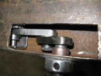
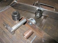
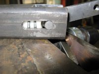
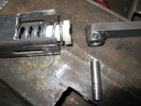
The side plates (the actuall angular parts that engage the SS) are rectangular tubes, 2x4". I had the shop cut the angles for me to make sure they were true. The lock pins are connected to each other by a tube so that both can be released by one handle.
Pictures and more details next.
Cheers,
Mike
My dad also recently purchased a 'bota L3400 with the crappy 3ph
and a pinned-on bucket - they don't have a QA for his loader. I looked at the aftermarket SS adapters but I don't like how far the push the bucket out; this would not be too big of a deal on the Montana (because it already has a QA) but the already marginal L3400 loader would loose to much lift, etc. I decided that I would design and build my own.My design is based around the following:
1. Has to be simple - use standard materials available with no special tools required ('normal' people don't have mills, surface grinders, etc
)2. The basic form of the SS assembly and lock mechanism has to be compatible or easily adapted to any loader configuration (width) for compact tractors (probably 25 to 50 hp).
3. Light weight
4. Only one release handle is needed to operate both lock pins
5. If possible, allow the possibility of adding a power lock/unlock feature
The following tools are required to build: disk grinder, chop saw, welder, drill press (max 7/8 hole is required). I also have a small Myford lathe that I used to modify some parts but those parts are easily substituted for 'off the shelf' items.
This is a cross section view of the design (from AutoCad).
The side plates (the actuall angular parts that engage the SS) are rectangular tubes, 2x4". I had the shop cut the angles for me to make sure they were true. The lock pins are connected to each other by a tube so that both can be released by one handle.
Pictures and more details next.
Cheers,
Mike