Iplayfarmer
Super Member
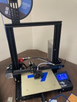
I started a backhoe project 13 years ago (Finally Building my Backhoe), and I'm finally working on finishing it. In those 13 years I have gained a few tools that have proven very valuable in the most recent stages of the build. One is an old Craftsman Atlas lathe. This has been great for turning bushings, pins, etc. Another is a 3D printer.
To be clear, I am not printing any of the parts for this build (so far). But I am printing a number of jigs and alignment guides. Square corners that land on easy measurements have been measured with the old traditional tape measure and tri-square, but there are some places in the design where I had to use weird measurements to make the geometry work out. A recent example is the tabs on the slew box that connect the box to the main frame. The tabs are cut from 3 inch bar stock with 30 degree angles. Then, the center of the bushings lands 1.89 inches away from the base of the tab.
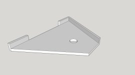
I printed the angle guide in the picture below to line my horizontal band saw up at exactly 30 degrees. I did the same thing with my outrigger feet that needed 22.5 degree angles. Next I'm printing a guide that I can place over the bracket to locate a pilot hole at 1.89 inches. I used this process for the tabs where the cylinders mount, and it worked well. I've also printed a jig that helps me cut angles on the ends of 2.5" square tube to allow things to pivot without interferance.
It helps that I have the whole backhoe drawn out in Sketchup. When I need a jig or guide, it's usually pretty quick to extract something out of the Sketchup model. I may eventually print some brackets or grommets for hydraulic hoses to go through, but for now the 3D printer has just been printing tools for me to use in the fabrication process.
To be clear, I am not printing any of the parts for this build (so far). But I am printing a number of jigs and alignment guides. Square corners that land on easy measurements have been measured with the old traditional tape measure and tri-square, but there are some places in the design where I had to use weird measurements to make the geometry work out. A recent example is the tabs on the slew box that connect the box to the main frame. The tabs are cut from 3 inch bar stock with 30 degree angles. Then, the center of the bushings lands 1.89 inches away from the base of the tab.
I printed the angle guide in the picture below to line my horizontal band saw up at exactly 30 degrees. I did the same thing with my outrigger feet that needed 22.5 degree angles. Next I'm printing a guide that I can place over the bracket to locate a pilot hole at 1.89 inches. I used this process for the tabs where the cylinders mount, and it worked well. I've also printed a jig that helps me cut angles on the ends of 2.5" square tube to allow things to pivot without interferance.
It helps that I have the whole backhoe drawn out in Sketchup. When I need a jig or guide, it's usually pretty quick to extract something out of the Sketchup model. I may eventually print some brackets or grommets for hydraulic hoses to go through, but for now the 3D printer has just been printing tools for me to use in the fabrication process.