whiz kid mathematical types please

   / whiz kid mathematical types please #1  

wroughtn_harv

Super Member
Joined
May 12, 2002
Messages
6,092
Location
Denison, Texas
Tractor
2013 Volvo MC85C
Boy I bet that's got the woodwork shaking./w3tcompact/icons/laugh.gif

Here's the sitchyation.

My tractor's a JCB165HF. I call her Iris cause, well, my grandma on my mama's side was called Iris.

She's a skid steer sorta like a Bobcat if someone capable of thinking out of the box had designed her.

The problem with drilling holes with a skid steer is they are designed for lifting, not pushing down.

For some time I've been thinking along the line of adding weight to the front lifting arm and then ingenuously devising a way to extend it out front compounding the weight, sorta like that Don guy did down there in God's country outside of Austin.

Man that's a lot of complicated thinking. Got myself a headache even trying to figure all the ins and outs of that configuring.

So now I've decided I'm gonna be simple.

The bottom of the tractor is protected by a solid belly pan front to back. There are two scupper kinds of pieces that run front to back on each side that are for draining debris etc.

I'm thinking about putting a couple of pieces of heavy wall rectangular tube, say three by four quarter wall along the scupper thingys.

In these will be other pieces of steel tube that slide in and out.

Here's the thought. When I need to apply down pressure on the auger I manually slide the inner tubes out to the rear. I pin these in place.

On the end of these tubes I have a method of attaching a pad.

What this does is when I apply the down pressure on the auger instead of the tractor raring up like a goosed pony and taking weight off the auger the arms out the back with the pads pick up the weight of the tractor and transfer it back to the auger.

Yup, I thought of that. Bent tubular arms are a definate for sure maybe most likely. It just so happens I have a couple of good points up high on the back of the cab to attach two other arms to angle down and back to the pads to pick up the bulk of the weight transfer.

I'm thinking I'd like this to be a simple pull tubes and pin kind of thing without any need for additional hydraulics and controls etc. I figure if the pads can be four feet off the back of the tractor and four inches or so off the ground I'll just have to be aware in tight spaces.

The pads won't be activated until they're needed when the weight transfer initiates them into place.

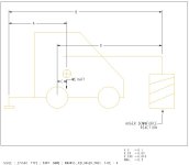
Here's the math part. Tractor weighs fifty four hundred pounds. It's about ten feet long. With a skid steer the bulk of the weight is around and behind the rear wheels. As I said, it's for lifting.

Now the shorter the distance from the rear of the tractor the pads are located the easier it's gonna be on everything involved. So if someone can figure out the down pressure with the pads at say two feet back versus three feet and even four feet.

I'm not real good at this word drawing stuff. But I'm even worse at the computer drawing.

A little help will be appreciated.

Keep in mind. This modification will only be needed when I'm in serious rock, which isn't that often. It's just that when you need it bygawd you need it.

I generally know when I'm gonna be in an area where there might be rock. So this thing will be one of those deals where hopefully it'll be just a matter of minutes to set it up. With the pads four inches off the ground I'll still be plenty mobile for moving hole to hole. But if and or when I hit rock it will only be a matter of applying downforce to go from bushel baskets of grins instead of truckloads of bad words.
 
   / whiz kid mathematical types please #2  
OK......how about this: You put a pad on the OPPOSITE end of the tractor as the auger is. By applying downpressure on this pad, you "bridge" the tractor from the pad to the auger, only leaving enough track touching the ground to keep the tractor from flopping over sideways. The weight of the tractor will be evenly divided....half to the auger, half to the pad. .....Dave
 
   / whiz kid mathematical types please #3  
Cj that is what he is talking about doing.
Since the CG (center of gravity) is about the rear wheels on
a SSL.
If u want half the weight on auger, the distance from auger to rear axle would be same as pad to rear axle.
If this distance is different divide the two to get the
% on auger or pad.
Hope this helps.
 
   / whiz kid mathematical types please #4  
EXACTAMENTO, thanks for making that point so clear.** OR.....how about TWO pads so that the auger and the pads act as a "tripod" and that way he can drill on any surface, regardless of the slope.
 
   / whiz kid mathematical types please
  • Thread Starter
#5  
So I guess the further back I go with the pads the more weight will be on the auger?????????

That makes sense. I was trying to find out how far back I'd have to go to get the various weights to the auger.

I've since decided that the heavier tubes will come from the top back of the tractor down. The horizontal tubes will just be locators and actually won't be carrying any weight.

These things will appear like wheely bars on a drag car when I'm driving around the job site.
 
   / whiz kid mathematical types please #6  
<font color=blue>So I guess the further back I go with the pads the more weight will be on the auger?????????</font color=blue>

Yup.

I did up a drawing for you, but can't convert it to a jpg. I have it in powerpoint if you want I can email it to you. My email is in my profile or send me a PM. I'll try to describe it here.

This problem is solved by what we mechanical engineers call a Free Body Diagram (FBD). To simplify we will assume that IRIS isn't accelerating, then we can apply two rules.

1. The sum of the forces = 0
2. The sum of the momements (torque) = 0

To calculate the maximum downforce, lets assume that you are able to lift both wheels off the ground (you may not be able to). Then we calculate moments at your pads sticking out the back of the tractor

There are two moments acting at this point

1. The distance between the pad and the Center of Gravity of IRIS (I will assume that it is slightly ahead (6") of the rear wheel). This is Dimension "A" in my drawing. = 3.5 ft X 5400 lb = 18,900 ft-lbs

2. the distance between the pad and the auger (dim "B" in my drawing) X auger downforce. = 10 ft * ???? We are trying to solve for the auger downforce so we use rule 2. The sum of the moments = 0 this means that moment 1 + moment 2 = 0.

Here's the algebra

A*Weight + B*Downforce = 0
rearrange A*Weight = -B*Downforce
Downforce = (-A*Weight)/B
The negative sign just keeps track of the direction of the force.

In numbers = (-3.5*5400)/10
= 1890 pounds

If you go to 4' behind
= (4.5*5400)/11 (this number gets bigger as you move the pad back)
= 2209 pounds

For reference w/o the pads there use the rear wheel as the pivot point to sum the moments (Dims C & D in my drawing)
downforce = (-C*weight)/D
= (-.5*5400)/7
= 385 pounds

BIG DIFFERENCE.

I guestimated at these dimensions, so pleas take out your tape measure or your highly calibrated eye & insert your numbers.
 
   / whiz kid mathematical types please #7  
Found a converter on the web. Drawing is attached
 

Attachments

  • 53-200582-wharv_jcb_auger_pads.jpg
    53-200582-wharv_jcb_auger_pads.jpg
    40.4 KB · Views: 227
   / whiz kid mathematical types please #8  
Now if for the full picture (and to help you size your tubes) you can calculate the reaction force at the pad using rule 1

Pad force + Weight + Auger Downforce Reaction = 0

The weight is pushing down & the reaction forces from the ground at the pad and auger are pushing up this means they will have different signs (+/-)

Weight - pad force - auger downforce = 0
Pad force = Weight - Auger downforce
So somewhere near 3,500#
 
   / whiz kid mathematical types please #9  
Hazmat
Thanks for the great explanation and formulas for calculating the forces involved. I wish had known these for a few past projects. Now the next question, is there a formula or table somewhere to calculate the strength of steel tubing/flat/pipe/etc? So that you know it will be able to withstand 3500lbs without bending.

Tim
 
   / whiz kid mathematical types please #10  
This is off the subject but what converter did you use. A DWG to jpg? I could use somthing like this quite a bit.

Thanks
Tim
 
   / whiz kid mathematical types please #11  
<font color=blue>Thanks for the great explanation and formulas for calculating the forces involved. I wish had known these for a few past projects. Now the next question, is there a formula or table somewhere to calculate the strength of steel tubing/flat/pipe/etc? So that you know it will be able to withstand 3500lbs without bending.</font color=blue>

Actually anything will bend when you apply a force, the question is how much will it bend? It is a bit detailed to get into here, I recommend you pick up a "mechanics" textbook at your local library. You'll have better luck finding one at a college library. The sub- subjects are statics (stationary) and dynamics (moving).

<A target="_blank" HREF=http://www.amazon.com/exec/obidos/tg/detail/-/0534371337/qid=1034085130/br=1-12/ref=br_lf_b_12//002-7437373-6458468?v=glance&n=491348>Mechanics Book at Amazon</A>

The "Bible" for mechanical engineering is <A target="_blank" HREF=http://www.amazon.com/exec/obidos/tg/detail/-/0070049971/qid=1034085430/sr=8-1/ref=sr_8_1/002-7437373-6458468?v=glance&n=507846> Mark's Handbook </A> However, this is a reference book, it assumes you have already learned the stuff in it. The textbook is a better way to educate yourself.

here is a web site with some info <A target="_blank" HREF=http://www.efunda.com/home.cfm>Efunda</A>
 
   / whiz kid mathematical types please #12  
<font color=blue>This is off the subject but what converter did you use. A DWG to jpg? I could use somthing like this quite a bit.</font color=blue>

Actually I used a tiff to jpeg converter. ProE will let me save a drawing as a tiff. Do a google search, I'm sure what you want is out there somewhere. Autocad may even have a plug in.
 
   / whiz kid mathematical types please #13  
Hazmat
Thanks for the suggested books and the website. Too bad Efunda charges for access to their website. It looks like it contains a lot of useful information. I may have became a paid member.

I was hoping there was a relatively easy formula/calculator were you could enter a constant for a particular steel type & shape from a table, the force that would be applied, and length of steel. That would give the amount of deflection for a span and usage type(ex. cantilever). After looking at efunda I see that I was probably over simplifying the math and physics involved.

Tim
 
   / whiz kid mathematical types please #14  
Here is the formula for a cantilevered beam with a point load on the end

deflection = (Load*length^3)/(3*E*I)

E = Modulus (material specific) typical value for steel = 30,000,000 lb/in^2

I = Moment of inertia (geometry specific ie I beam vs. rect. tubing etc.) for a rectangle = (BH^3 -bh^3)/12

B = base of outside
H = Height of outside
b= base of inside rectangle
h= height of inside rectangle
 
   / whiz kid mathematical types please #15  
Thanks Hazmat!!! I guess that doesn't look too difficult. But there must be a large number of formulas depending on material shape and usage (cantilevered, simple span with 2 end points, etc.)

So is following correct for Harv's example?

3500 lbs of force
4' back from the center of gravity
If he used a single 3" x 3" x 1/4" steel tube the end of the tube would deflect .106 inches.
If he used 2 equal tubes and the force was equal on both, each tube would deflect .053 inches.

I = (BH^3 -bh^3)/12
I = ((3" x 3")^3 - (2.5" x 2.5")^3) / 12
I = (729 - 244) / 12
I = 40.4

Note: I presume the length needs to be in inches to keep the units consistant, so I multiplied 4' x 12
deflection = (Load*length^3)/(3*E*I)
deflection = (3500 x (4' x 12)^3 ) / (3 x 30,000,000 x 40.4)
deflection = .106 in

Would a .106" deflection on a 4' piece of steel tubing cause a perminent deformation (bend) after the force was removed?
 
   / whiz kid mathematical types please #16  
<font color=blue>But there must be a large number of formulas depending on material shape and usage (cantilevered, simple span with 2 end points, etc.)</font color=blue>

Yup, different formula for each application. The equation changes for cantilevered vs. simple span & point loading vs. uniform loading etc.

The moment of Inertia (I) changes based on the geometry of the beam (rectangle vs. I beam vs. pipe).

<font color=blue>Would a .106" deflection on a 4' piece of steel tubing cause a perminent deformation (bend) after the force was removed?</font color=blue>

My first guess is no. But we need to caculate the stress. According to my Marks handbook, The shear = W = 3500 lbs. Then we need to divide by the cross sectional area to get the shear stress = 3500/2.75in^2 = 1272 PSI. A36 steel has a yield point of 36,000 psi. So WHarv can use even smaller steel if he wants to.

If we were really good we'd use Mohr's circle to calculate the combined stresses (tension and torsion), but since 1272 psi is so low compared to 36,000 there is no need to.

So Harv, if this works, & I need I new fence some day, you may need to plan a vacation w/ IRIS to New England/w3tcompact/icons/grin.gif
 
   / whiz kid mathematical types please
  • Thread Starter
#17  
Thanks Stephen,

I figured the thirty five hundred pound load was where I wanted to be, nice round number.

I was looking at the tractor yesterday and decided how I was going to build the assembly I needed.

The two primary pieces are going to be attached and pivot two hundred and seventy degrees along the rear roof line of the canopy. Right next to where the lift hooks are located. You have to figure if that place is stout enough to lift the tractor then it's also stout enough to attach a jack for lifting the tractor/w3tcompact/icons/smile.gif.

They will collapse, one tube into another, and lay along the roof when not needed. When needed they will fold over and down and then extend out to the desired length for attaching the pad.

Right now I'm thinking two rods attached at the bottom back of the tractor are what I need to locate the pads front to back. After all when the pads are functioning to lift the back of the tractor the rods will be in tension which is probably they're strongest trait. The two arms coming off the back top will be in compression, the second strongest trait of the tubing if I'm thinking straight.

This allows me to use smaller lighter than if I was wanting to rely on twisting or bending of the tube to do work.

The pads will either be bowl shaped or if I can find some, short squatty body wheels. The tractor lifts in an arc. I can move it back and forth on the pads if they're bowl shaped or even better wheels with just the actions of the boom to keep the hole plumb.
 

Tractor & Equipment Auctions

2001 John Deere M665 60in Zero Turn Commercial Mower (A59228)
2001 John Deere...
excavator trenching bucket- one bucket per lot (A56438)
excavator...
2022 FORD F-250 STV CREW CAB TRUCK (A59823)
2022 FORD F-250...
2017 KINZE KNOTCHED SINGLE DISK FERTILIZER OPENER FOR 3000/3500 SERIES PLANTERS (6 ROWS) (A55315)
2017 KINZE...
Ford F450 Bucket Truck with Altec AT200A Boom (A56435)
Ford F450 Bucket...
2014 Ford Fusion Passenger Car, 2.5L Engine - Only 90,875 Miles (A56438)
2014 Ford Fusion...
 
Top