Yogi05
Elite Member
2008 Foton TB504
Tractor has factory cab so switches etc. are not exposed directly to weather.
Front work lights and headlights work intermittently.
Left side signal and hazards not at all.
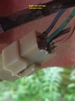
Right side signal and hazards work but the relay buzzes unless you press it in firmly.
I have been taking this in sections but without a specific schematic it's the Devil's work.
I have the dash removed and harnesses available. I suspect I have multiple corroded connectors.
I got a 2 pin flasher as a replacement for the 3 pin. It works OK but only the right side lights work (as has been the case).
With a test light there is a solid battery feed to the relay, but with the flasher (2 or 3 pin) installed
there is a very low light from the test light on the "load" wire (the wire out of the flasher to the switches) when the haz or signal switches are off.
This to me indicates a power bleed.
I figure I'm looking for one or more corroded connectors, so I started with the right rear tail light lens because
A corroded wire fell off that one already while poking at it.
My mystery (or mistake)
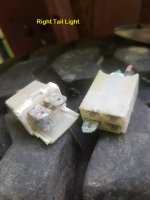
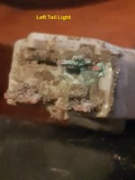
I took the lens out, cut the corroded screws holding the cover on the back so I could access sockets and checked for corrosion.
One socket is a touch rusty along the sides but the isolator for the center contact is clean.
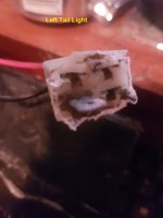
Using an OHM meter I checked all the wires in the 3 sockets.
I touched the meter to the ground wire, (which is spliced together from all 3 sockets) and the other lead to each individual positive wire.
It was OK.
Then I touched the meter lead to one of the positive wires and the other lead to each of the other positive wires. This showed continuity
between the blue, red and yellow wires with the bulbs in.
I even installed one bulb at a time and checked just to make sure a bulb didn't have a shorted filament I couldn't see.
To me this should not be. It is essentially telling me all the wires from the center contact in each socket are joined. This could be my
mistake and normal, so I stand to be informed. This was all done on a bench with no battery power. Just an OHM meter.
A specific schematic would make this all easier. I could actually follow the flow. The wires change color from one side of a connector to the other on this machine.
Very frustrating.
Appreciate any help.
Tractor has factory cab so switches etc. are not exposed directly to weather.
Front work lights and headlights work intermittently.
Left side signal and hazards not at all.
Right side signal and hazards work but the relay buzzes unless you press it in firmly.
I have been taking this in sections but without a specific schematic it's the Devil's work.
I have the dash removed and harnesses available. I suspect I have multiple corroded connectors.
I got a 2 pin flasher as a replacement for the 3 pin. It works OK but only the right side lights work (as has been the case).
With a test light there is a solid battery feed to the relay, but with the flasher (2 or 3 pin) installed
there is a very low light from the test light on the "load" wire (the wire out of the flasher to the switches) when the haz or signal switches are off.
This to me indicates a power bleed.
I figure I'm looking for one or more corroded connectors, so I started with the right rear tail light lens because
A corroded wire fell off that one already while poking at it.
My mystery (or mistake)
I took the lens out, cut the corroded screws holding the cover on the back so I could access sockets and checked for corrosion.
One socket is a touch rusty along the sides but the isolator for the center contact is clean.
Using an OHM meter I checked all the wires in the 3 sockets.
I touched the meter to the ground wire, (which is spliced together from all 3 sockets) and the other lead to each individual positive wire.
It was OK.
Then I touched the meter lead to one of the positive wires and the other lead to each of the other positive wires. This showed continuity
between the blue, red and yellow wires with the bulbs in.
I even installed one bulb at a time and checked just to make sure a bulb didn't have a shorted filament I couldn't see.
To me this should not be. It is essentially telling me all the wires from the center contact in each socket are joined. This could be my
mistake and normal, so I stand to be informed. This was all done on a bench with no battery power. Just an OHM meter.
A specific schematic would make this all easier. I could actually follow the flow. The wires change color from one side of a connector to the other on this machine.
Very frustrating.
Appreciate any help.
")
 . eh
. eh