Henro
Super Member
- Joined
- Jul 4, 2003
- Messages
- 5,007
- Location
- Few miles north of Pgh, PA
- Tractor
- Kubota B2910, BX2200, KX41-2V mini EX
I am torn between posting and not posting what I am doing with my own, personal, T&T project. There has been so much posted in the past on the same type project. Still, I think mine may be a little different, as I have focused on keeping things matched to the relatively small 3PH on my B2910 Kubota, and decided that to attain that goal I would have to use two tilt cylinders.
But before I start posting photos and all that, here are some links that will tell more than this thread will ever attempt to. By the time you read them you will probably have your fill and turn to a different thread!
Bird’s “Tip & Tilt” thread:
http://www.tractorbynet.com/forums/showflat.php?Cat=0&Board=owning&Number=24170&fpart=1&PHPSESSID=
Bird’s Second “Tip & Tilt” thread:
http://www.tractorbynet.com/forums/showflat.php?Cat=0&Board=owning&Number=32151&fpart=1&PHPSESSID=
Bill_in_MI’s thread:
http://www.tractorbynet.com/forums/showflat.php?Cat=0&Board=owning&Number=52842&fpart=1&PHPSESSID=
Glenmac’s thread
http://www.tractorbynet.com/forums/showflat.php?Cat=0&Board=custom&Number=59298&fpart=1&PHPSESSID=
Hayden’s “Going down the Top N Tilt path” thread:
http://www.tractorbynet.com/forums/showflat.php?Cat=0&Board=custom&Number=46715&fpart=1&PHPSESSID=
Hydraulic fittings Qs.
http://www.tractorbynet.com/forums/showflat.php?Cat=0&Board=buildit&Number=220085&fpart=1&PHPSESSID=
Hydraulic top link questions
http://www.tractorbynet.com/forums/showflat.php?Cat=0&Board=custom&Number=258418&fpart=1&PHPSESSID=
Hydraulic Valve Options
http://www.tractorbynet.com/forums/showflat.php?Cat=0&Board=custom&Number=65437&fpart=1&PHPSESSID=
Lock Valve (double piloted checkvalve) Plumbing
http://www.tractorbynet.com/forums/showflat.php?Cat=0&Board=parts&Number=397234&fpart=1&PHPSESSID=
Hydraulic side link is too sensitive
http://www.tractorbynet.com/forums/showflat.php?Cat=0&Board=implement&Number=244220&fpart=1&PHPSESSID=
ARGGGH....Where can I get flow restrictors for HTL
http://www.tractorbynet.com/forums/showflat.php?Cat=0&Board=parts&Number=426811&fpart=1&PHPSESSID=
Rear remotes + TNT for B-series tractors by MadReferee
http://www.tractorbynet.com/forums/showflat.php?Cat=0&Board=owning&Number=397828&fpart=1&PHPSESSID=
Apologies to those whose threads I somehow did not find.
Now that the housekeeping is out of the way, let me state my goals, which were:
I could not afford to lose anything by installing the T&T, and I still really wanted to end up with a good T&T setup when I was done. Sounds like something is crossed up there. But after thinking about it, and seeing that my tractor is relatively small, I realized I could not afford to lose 3PH-lift capability for the sake of T&T. If I had had to give up 3PH-lift capacity, then I guess I would have passed on the tilt part of the T&T idea. I still probably would have installed a hydraulic the top link though.
Fortunately, I was able to come up with a set up that actually gives me about 0.75 inch more lift (at the lift rod ends) than I have in the stock set up.
From what I have read, most T&T setups on small tractors end up sacrificing 3PH-lift capacity. Generally, I think it is fair to say that a tilt cylinder, with ample stroke, is put on one side, and then the adjustable lift rod (that is standard on most tractors) is put on the other side. That mechanical lift rod is adjusted so the 3PH will be level when the tilt cylinder is at mid stroke. The net result seems to be that some lift capability is lost. (This may not be true in all cases. It is just my unscientific observation.)
So with a smaller size 3PH, things often end up where the new point at which level is found will be physically lower than the level point of the original equipment. Net result: The 3PH does not lift as high as it did before the T&T was installed. Not a good thing on a small tractor with limited 3PH lift to begin with. Not that the B2910 Kubota I am putting this on is that limited. But it is certainly more limited than a larger tractor is.
Additionally, I wanted a way to be sure that my 3PH were level without thinking too much about it. I was not sure I could see a mechanical level indicator if I devised one for use on one tilt cylinder. However, two tilt cylinders, each with its own control valve, would allow me to simply retract them both fully and to know without question that the 3PH was level, with respect to the rear axle. I would not even have to look if I did not want to. Level is something I don’t currently know if I attained or not without measuring, even with the standard mechanical tilt setup. So the new T&T offers an Advantage! Actually two advantages, certain level and more lift than stock.
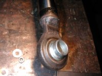
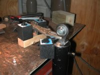
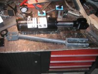
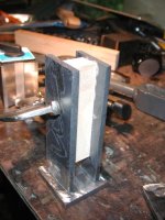
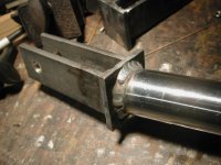
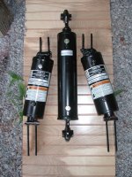
After reading all the threads I pointed at above, several times, I concluded that a single tilt cylinder with a 4-inch stroke would probably be adequate for my needs. But if I went with two cylinders, each with a 2-inch stroke, I could actually gain (a fair amount of) lift on the 3PH, so I set the goal of finding cylinders with 2-inch stroke for my application. Fortunately they are not common. What is fortunate about not finding what you want? Well, I did not know it at the time, but when welding ends on the cylinder rod, with even four inches of rod outside the cylinder, you need to be very careful not to overheat the cylinder seals. I doubt I could have avoided cooking cylinder seals on a cylinder with only 2-inches of stroke, without making some kind of special cooper, water-cooled heat sink to put around the rod. With the 4-inch stroke, I was able to get buy with an old pair of wet underwear as the heat sink, along with taking some time between welds to let things cool off a bit.
Actually, even when using cylinders with a 4-inch stroke on each side, I was able to gain about 0.75-inch lift over the stock setup. So I will have gained with putting T&T on my tractor. This 2-tilt-cylinder setup will give equal tilt capability in each direction, and a bit more lift than the stock setup had to boot. Along with a simple way of putting the implement at level, by simply raising both tilt cylinders fully.
As I type this, the T&T is not quite finished, but it is close. I ordered the necessary hoses and fittings to complete the job (I hope, major headache being sure of what I needed) and expect to receive them shortly.
When putting my system together I have tried to approach this with an open mind and my system has evolved along slightly different lines than those of past posters. I hope this report will be of interest. I took a lot of pictures and will post some of them, as I guess you guys are like me and enjoy looking a pictures of what others are doing.
The time sequence may jump around a bit since I am a bit along in the project, so please bear with me.
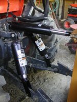
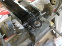
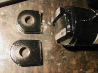
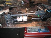
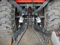
I’ll start with a picture of the three cylinders on the tractor, taken when I was checking out my progress to that point. Then I’ll back tract and show how I got to that point, and take it from there.
But before I start posting photos and all that, here are some links that will tell more than this thread will ever attempt to. By the time you read them you will probably have your fill and turn to a different thread!
Bird’s “Tip & Tilt” thread:
http://www.tractorbynet.com/forums/showflat.php?Cat=0&Board=owning&Number=24170&fpart=1&PHPSESSID=
Bird’s Second “Tip & Tilt” thread:
http://www.tractorbynet.com/forums/showflat.php?Cat=0&Board=owning&Number=32151&fpart=1&PHPSESSID=
Bill_in_MI’s thread:
http://www.tractorbynet.com/forums/showflat.php?Cat=0&Board=owning&Number=52842&fpart=1&PHPSESSID=
Glenmac’s thread
http://www.tractorbynet.com/forums/showflat.php?Cat=0&Board=custom&Number=59298&fpart=1&PHPSESSID=
Hayden’s “Going down the Top N Tilt path” thread:
http://www.tractorbynet.com/forums/showflat.php?Cat=0&Board=custom&Number=46715&fpart=1&PHPSESSID=
Hydraulic fittings Qs.
http://www.tractorbynet.com/forums/showflat.php?Cat=0&Board=buildit&Number=220085&fpart=1&PHPSESSID=
Hydraulic top link questions
http://www.tractorbynet.com/forums/showflat.php?Cat=0&Board=custom&Number=258418&fpart=1&PHPSESSID=
Hydraulic Valve Options
http://www.tractorbynet.com/forums/showflat.php?Cat=0&Board=custom&Number=65437&fpart=1&PHPSESSID=
Lock Valve (double piloted checkvalve) Plumbing
http://www.tractorbynet.com/forums/showflat.php?Cat=0&Board=parts&Number=397234&fpart=1&PHPSESSID=
Hydraulic side link is too sensitive
http://www.tractorbynet.com/forums/showflat.php?Cat=0&Board=implement&Number=244220&fpart=1&PHPSESSID=
ARGGGH....Where can I get flow restrictors for HTL
http://www.tractorbynet.com/forums/showflat.php?Cat=0&Board=parts&Number=426811&fpart=1&PHPSESSID=
Rear remotes + TNT for B-series tractors by MadReferee
http://www.tractorbynet.com/forums/showflat.php?Cat=0&Board=owning&Number=397828&fpart=1&PHPSESSID=
Apologies to those whose threads I somehow did not find.
Now that the housekeeping is out of the way, let me state my goals, which were:
I could not afford to lose anything by installing the T&T, and I still really wanted to end up with a good T&T setup when I was done. Sounds like something is crossed up there. But after thinking about it, and seeing that my tractor is relatively small, I realized I could not afford to lose 3PH-lift capability for the sake of T&T. If I had had to give up 3PH-lift capacity, then I guess I would have passed on the tilt part of the T&T idea. I still probably would have installed a hydraulic the top link though.
Fortunately, I was able to come up with a set up that actually gives me about 0.75 inch more lift (at the lift rod ends) than I have in the stock set up.
From what I have read, most T&T setups on small tractors end up sacrificing 3PH-lift capacity. Generally, I think it is fair to say that a tilt cylinder, with ample stroke, is put on one side, and then the adjustable lift rod (that is standard on most tractors) is put on the other side. That mechanical lift rod is adjusted so the 3PH will be level when the tilt cylinder is at mid stroke. The net result seems to be that some lift capability is lost. (This may not be true in all cases. It is just my unscientific observation.)
So with a smaller size 3PH, things often end up where the new point at which level is found will be physically lower than the level point of the original equipment. Net result: The 3PH does not lift as high as it did before the T&T was installed. Not a good thing on a small tractor with limited 3PH lift to begin with. Not that the B2910 Kubota I am putting this on is that limited. But it is certainly more limited than a larger tractor is.
Additionally, I wanted a way to be sure that my 3PH were level without thinking too much about it. I was not sure I could see a mechanical level indicator if I devised one for use on one tilt cylinder. However, two tilt cylinders, each with its own control valve, would allow me to simply retract them both fully and to know without question that the 3PH was level, with respect to the rear axle. I would not even have to look if I did not want to. Level is something I don’t currently know if I attained or not without measuring, even with the standard mechanical tilt setup. So the new T&T offers an Advantage! Actually two advantages, certain level and more lift than stock.
After reading all the threads I pointed at above, several times, I concluded that a single tilt cylinder with a 4-inch stroke would probably be adequate for my needs. But if I went with two cylinders, each with a 2-inch stroke, I could actually gain (a fair amount of) lift on the 3PH, so I set the goal of finding cylinders with 2-inch stroke for my application. Fortunately they are not common. What is fortunate about not finding what you want? Well, I did not know it at the time, but when welding ends on the cylinder rod, with even four inches of rod outside the cylinder, you need to be very careful not to overheat the cylinder seals. I doubt I could have avoided cooking cylinder seals on a cylinder with only 2-inches of stroke, without making some kind of special cooper, water-cooled heat sink to put around the rod. With the 4-inch stroke, I was able to get buy with an old pair of wet underwear as the heat sink, along with taking some time between welds to let things cool off a bit.
Actually, even when using cylinders with a 4-inch stroke on each side, I was able to gain about 0.75-inch lift over the stock setup. So I will have gained with putting T&T on my tractor. This 2-tilt-cylinder setup will give equal tilt capability in each direction, and a bit more lift than the stock setup had to boot. Along with a simple way of putting the implement at level, by simply raising both tilt cylinders fully.
As I type this, the T&T is not quite finished, but it is close. I ordered the necessary hoses and fittings to complete the job (I hope, major headache being sure of what I needed) and expect to receive them shortly.
When putting my system together I have tried to approach this with an open mind and my system has evolved along slightly different lines than those of past posters. I hope this report will be of interest. I took a lot of pictures and will post some of them, as I guess you guys are like me and enjoy looking a pictures of what others are doing.
The time sequence may jump around a bit since I am a bit along in the project, so please bear with me.
I’ll start with a picture of the three cylinders on the tractor, taken when I was checking out my progress to that point. Then I’ll back tract and show how I got to that point, and take it from there.