That Never Ending T&T Path!

   / That Never Ending T&T Path!
  • Thread Starter
#21  
Final configuration for assembly. The O-rings come with each valve section in a little bag like you see in this picture.
 

Attachments

  • 506173-A (20).jpg
    506173-A (20).jpg
    48.1 KB · Views: 654
   / That Never Ending T&T Path!
  • Thread Starter
#22  
After beating the issue of where I was going to position my control valve, I decided to mount it overhead neat the top of my ROPS, under the head protector. I do not foresee the need to ever fold my ROPS so this will work OK for me. I fabricated a mounting bracket that would hold the valve. Here it is before painting.
 

Attachments

  • 506174-A (21).jpg
    506174-A (21).jpg
    79.1 KB · Views: 699
   / That Never Ending T&T Path!
  • Thread Starter
#23  
Control valve assembled and primed, waiting for a coat of black paint. The mounting bracket is ready to be bolted on the tractor. Things are progressing nicely, albeit slowly.
 

Attachments

  • 506175-A (22).jpg
    506175-A (22).jpg
    79.7 KB · Views: 592
   / That Never Ending T&T Path!
  • Thread Starter
#24  
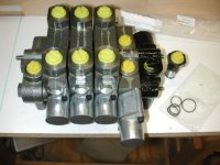
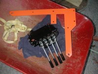
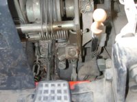
Control valve mounted in what I know is an unconventional position. It was OK, but the handles were a little close to my head. I decided to move it towards the back by about seven inches. This distance was determined by the spacing of the mounting holes on the valve. The valve has been hanging there for a couple weeks now and I don’t notice it at all, so I think it will work fine there.

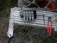
Now it is almost counterintuitive that a valve put in this position would be functional. But when I twist around to look back and test it, my hand hangs comfortably there so I am hopeful it will work fine for me.

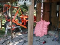
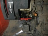
One thing we should all keep in mind is that when the tractor is working, the hydraulic fluid gets quite hot and can burn skin off pretty easily. I will have all my hoses shielded in some fashion, and plan on fabricating a guard in front of the hoses on the valve assembly as well, to deflect a leak should one occur. This is something I would do even if the valve and hoses were down on the fender, but it is even more important to do it when the valve and hoses are elevated like I am doing.
 

Attachments

  • 506177-A (23).jpg
    506177-A (23).jpg
    73.8 KB · Views: 762
   / That Never Ending T&T Path!
  • Thread Starter
#25  
The valve and mounting bracket were taken back off and an extra piece of 0.25 x 2 inch flat bar was welded on, so the valve could be shifted towards the back. A simple enough modification really, and the net result is a great improvement from what I can see.
 

Attachments

  • 506179-A (24).jpg
    506179-A (24).jpg
    59.7 KB · Views: 598
   / That Never Ending T&T Path!
  • Thread Starter
#26  
The control valve in its new position. From what I can see it will be perfect here. I can still reach it easily from the ground when standing beside the tractor, and it is back far enough that it is totally out of the way as far as possible interference with my head goes.
 

Attachments

  • 506180-A (25).jpg
    506180-A (25).jpg
    85.1 KB · Views: 633
   / That Never Ending T&T Path!
  • Thread Starter
#27  
This picture is specific to Kubota B2910 and B7800 owners, It shows the return-to-tank point on the side of the tractor. It is a bit congested there on my tractor due to the cruise control assembly. I ended up taking the return hose from the loader off, and putting a run tee on the fitting, then re-threaded the hose from the loader up between some linkages and it seems to be fine that way. Here is a pic of the starting point.
 

Attachments

  • 506181-A (26).jpg
    506181-A (26).jpg
    50.4 KB · Views: 657
   / That Never Ending T&T Path!
  • Thread Starter
#28  
The Tee is in place and the original hose hooked back up. The 90 degree side of the tee is capped until I get ready to hook up the return hose from the new valve.
 

Attachments

  • 506182-A (27).jpg
    506182-A (27).jpg
    42.3 KB · Views: 599
   / That Never Ending T&T Path!
  • Thread Starter
#29  
The hoses to/from the control valve will run inside 3” ABS plastic pipe. Two reasons for this. One is protection of the hoses themselves. The second is protection of me should a hose break/puncture. I certainly do not want a 180 degree hot oil shower!
 

Attachments

  • 506183-A (29).jpg
    506183-A (29).jpg
    94.4 KB · Views: 583
   / That Never Ending T&T Path!
  • Thread Starter
#30  
I’m actually not yet sure exactly how I will shield the hoses in this location, but this is the prototype. I plan on using bulkhead fittings across the back of the tractor, behind and slightly below the seat. The hoses from the control valve will terminate there, and on the backside I will have a row of quick disconnects to which the hoses from the cylinders will attach.

It is my intention to have the control valve section with float available for use with either the top link or a tilt cylinder. I can see some worth using float on the top link when brush hogging, or possibly using float with a landscape rake or rear blade (when snow plowing). Time will tell.

More to follow (soon I hope)
 

Attachments

  • 506184-A (30).jpg
    506184-A (30).jpg
    89.4 KB · Views: 621
 
Top