Hydraulic Post Pounder

   / Hydraulic Post Pounder #1  

Spike-MI

New member
Joined
Nov 23, 2006
Messages
8
Location
Chelsea, Michigan
Tractor
JD4720, JD7920, JD6420
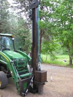
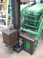
Okay, so I am cheap (and poor). I could not afford to buy a Vector Post Driver. The best price I could come up with was over $5k plus freight, ouch. So, I built one. As you will see by the photos, I modified Vector's loader-mount model. Theirs uses an offset design, which admittedly is better than mine, but very hard on the loader in my opinion. The big advantage of the offset is that you can drive right down the fence line. With my design the pounder is centered on the loader, so you have to square up to each post; you can't just drive down the line.

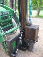
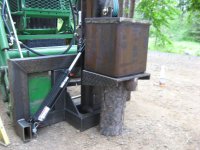
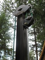
I designed the pounder with a 500lb weight and drop of 6'. The "as built" unit came out with a 530lb weight, and 68" of drop. Close enough. It has a 3/4" AR500 independent post cap that travels independent of the weight on the main mast. I also designed a tilt cylinder to adjust for changes in grade, with the hope I can actually drive the posts somewhat plumb.

By now you are probably wondering why I built one this large. Well, I have a fair amount of cattle fencing to do and I want to use railroad ties. This should easily develop enough force to drive a railroad tie blunt.

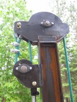
So, I am not posting to brag, but because my hyraulic design is not working and I need some expertise from you fellas. The system uses a 2" bore x 36" stoke 2500psi cylinder. It is set up as a single acting cylinder, kind of... The pressure line is used to retract the cylinder, which pulls down on block, which retracts the rope, and raises the weight. Once it reaches the top, I throw my auxillary valve in float and down goes the weight, VERY SLOWLY. It doesn't fall with gravity like I expected. I believe that I failed to consider is the rate at which the hydraulic flow is restricted as it pushed back to my tractor's main reservior. There must be enough restriction that the weight (all 530lbs of it) drops at about the same rate that it raises with the tractor at idle. However, even at that speed you don't want anything between the weight and the post cap plate because it sounds like hitting something with a 500lb sledge hammer. Just FYI I am using my factory front 3rd valve to run the pounder. It is plumbed from the rear of the tractor with 3/8" hard lines, and has 1/4" standard quick couplers on the loader. I ran a 3/8" flex hydraulic line with a 1/4" reducing quick coupler.

So my question to you much more skilled hydraulic TBN-er's is what is the easiest, cheapest fix to make this thing slam down like the Vector guys' post pounders do?

Here is a YouTube link to their mini excavator mount model in action: http://www.youtube.com/watch?v=pWnZvijS5nE&playnext=1&list=PL71AD198E95ECC30B

Look forward to your advice. Spike, now in Idaho not Michigan (but my heart's still there!)
 

Attachments

  • IMG_4435.JPG
    IMG_4435.JPG
    128.9 KB · Views: 30,800
  • IMG_4436.JPG
    IMG_4436.JPG
    119.2 KB · Views: 16,329
  • IMG_4438.JPG
    IMG_4438.JPG
    96.6 KB · Views: 110,235
  • IMG_4439.JPG
    IMG_4439.JPG
    89.7 KB · Views: 11,681
  • IMG_4441.JPG
    IMG_4441.JPG
    129.1 KB · Views: 12,486
  • IMG_4440.JPG
    IMG_4440.JPG
    107.7 KB · Views: 22,551
   / Hydraulic Post Pounder #3  
That what I would do too. In addition to it I would connect both sides of the cylinder to the hydraulics and use valve with regeneration feature to increase the speed of extension stroke.
 
Last edited:
   / Hydraulic Post Pounder #4  
I have seen guardrail pounder trucks and the cyl/pulley arrangement was setup similar but different....

They used a larger dia single acting ram (5 or 6 " dia IIRC) with the cyl positioned between two multiple pulley sheaves.......they used cable that was wrapped around the pulleys multiple times (4 or 5)to achieve a longer stroke/lift ratio ....kinda like a block and tackle with a cyl between the pulleys...

Google Image Result for http://www.photographers1.com/Sailing/BlockAndTackle.gif

I'm having a hard time to describe it but the principle would allow the cyl that stoked 12" to retract the weight 4-5'.......then using large hoses with large valve block with a direct return to tank (not through regular valve) would allow the oil to return to be unrestricted for quicker drops......
 
   / Hydraulic Post Pounder #5  
But if slower would work, make a latch for the weight. Retract the cylinder, raise the weight, latch it up, extend the cylinder, drop the weight, repeat.

Bruce

Thats what I was going to suggest when I first read your post! :thumbsup:
Something to hold the weight up until you can extend the cylnder all the way then drop it like a 1/4 ton of steel!! :laughing:
 
   / Hydraulic Post Pounder #6  
Thats what I was going to suggest when I first read your post! :thumbsup:
Something to hold the weight up until you can extend the cylnder all the way then drop it like a 1/4 ton of steel!! :laughing:
Good, but slow due to many needed repetitions. Current OP design should work well with an unobstructed return line ... no QCs, short, large diameter tubing, maybe a larger valve. Alternately a cyl sized for min required lift force would go faster.
larry
 
   / Hydraulic Post Pounder #7  
I'm not sure how to make it, but make some kind of trip release that when the pull cyl get to the bottom, a trip releases the cylinder from the carriage and the wieght free fall and pulls the carriage (pully and rope) fly up and hits a rubber or harder stop. then you have the cyl go back up to attach to the carriage and again start pull the carriage back down and the weight back up.
 
   / Hydraulic Post Pounder
  • Thread Starter
#8  
BCP- I think you are right, I just can't find the info I need to set up a "fast return." The issue that I think most of the replies are missing is that a "latch" and free fall system won't work. You simply can't get 30-40 strokes per minute out of a system like that. The Shaver post pounders and the Vector that I copied are using a similar system. The issue at hand is that fluid is only used on one side of the piston in a system like this one. The other side of the piston is dry. As the weight moves down it sucks in air through the breather which has no resistance. The only resistance (and my inherent problem) is forcing out the same fluid that just raised the weight, back through the pressure line and to the reservoir. If you look at the Vector drivers they don't attach a line to both ports of a cylinder, just the side to raise the weight. Still searching...
 
   / Hydraulic Post Pounder #9  
The Shaver post pounders and the Vector that I copied are using a similar system. The issue at hand is that fluid is only used on one side of the piston in a system like this one. The other side of the piston is dry. As the weight moves down it sucks in air through the breather which has no resistance.
The Shaver cyls are made differently than you describe. In the Shaver cylinder the thing we normally call a piston is essentially a triangular space frame affixed to the end of the rod. The rod is guided on its exit seal and the "piston". Incoming fluid is able to easily get to both sides of the piston. The net raise force thus achieved is the pressure times the rods area. Very little fluid is moved [and no air] during the 48" stroke -- maybe as much as a quart. ... Still, the flush during fall probably gets as high as 40gpm and needs a large return to reservoir. The speed of downward motion also would definitely be impeded by air being moved on a full area dry side of a normal piston cylinder as you describe. Since you are sucking air the force limits to ~45 pounds x 2 for the pulley arrangement. That 90# adds to the fluid flush loss.
larry
 
   / Hydraulic Post Pounder #10  
This is in the "just so you know department" not being critical here, but in using the wire rope clamps, (yes I know that is not wire rope) the minimum number is 3 and the way to put them on is so that the "dead end" is adjacent to the U clamp not the saddle part of the clamp. as in the old saying "Do not saddle a dead horse" as a way to remember it. The top ones are correct (but need 3) the bottom ones are incorrect, I am not sure how well they will hold with the nylon rope, but probably OK. Again not trying to start anything, just passing along standard practice.

James K0UA

http://www.sbic.com/smos/may06/smo060503.pdf
 
Last edited:
   / Hydraulic Post Pounder #11  
I think a better way to go would be using a hydraulic motor winding a cable much less oil to deal with, especially on the drop cycle, just thinkin outloud, Eric
 
   / Hydraulic Post Pounder #12  
Variable torque hydraulic motor with a swash plate shouldn't require any oil flow when in neutral.
 
   / Hydraulic Post Pounder #13  
Use a hydraulic motor and design the trip like a well drilling setup... just thinking outloud.
 
   / Hydraulic Post Pounder #14  
not sure if this would work or not, but if one used the standard valve to lift but near the cylinder, put in a Tee and a ball valve of the correct pressure ratting and dump the cylinder via the ball valve, using say a 3/4 return hose to the reservoir,

if there is additional restriction down hose on the return line one could dump it via the ball valve into the other port of the cylinder as well (thus acting like a reservoir for the ex caping oil) and then let the next charge stroke push the oil back to the tractor reservoir through the restrictions at a much slower rate,
 
   / Hydraulic Post Pounder #15  
This is in the "just so you know department" not being critical here, but in using the wire rope clamps, (yes I know that is not wire rope) the minimum number is 3 and the way to put them on is so that the "dead end" is adjacent to the U clamp not the saddle part of the clamp. as in the old saying "Do not saddle a dead horse" as a way to remember it. The top ones are correct (but need 3) the bottom ones are incorrect, I am not sure how well they will hold with the nylon rope, but probably OK. Again not trying to start anything, just passing along standard practice.

Learn something every day. Thanks k0ua :thumbsup:

As far as OP, the rig part of your build looks nice and clean, hope you get your hyd issue resolved. I think like others that a variable torque hydraulic motor with a swash plate would allow a free fall of the hammer. The design you based your build on? Does it use a hyd cylinder? If so maybe see what they do differently. Good luck.
 
   / Hydraulic Post Pounder #16  
I think most people are missing what the OP wants.....to be able to cycle 30 or 40 strokes a min.....he has a lot of posts to drive and a hydraulic motor/and or latch system would be way to slow... Used a few post knockers myself in the vineyard and had a couple of problems like this. The cure seemed to be to always made sure the return line was of a large size that went directly back to the hydraulic tank.

regards
 
   / Hydraulic Post Pounder #17  
I looked up the vector site a watched the video, Looks very fast only took 3 hits to set the post, dont see the need for 30/40 hits a minite, the key is droping a lota weight fast, the op has done a great job of copying the vector machine, figuring out the restrection is going to take more than a big *** return line he also needs a big *** valve, 3/4 / 1in ports, another thing that will need to be LARGE is the port coming out of the cylinder, dont matter how big the line/valve are, IF the oil cant get out of the cylinder, i think he said hes using a 2in bore cylinder, it probably has a 1/4 / 3/8 port, that should be 3/4 plus, not a big deal to bore the port and weld in a large one, imho Eric
 
   / Hydraulic Post Pounder #18  
First let me compliment you on your fabrication skills, and once you get it operating the way you want, I hope you paint it.

Another factor adding resistance is the seals and glands in the hydraulic cylinder. I agree with others saying you need a big unrestricted return oil line to dump the fluid back to the tank.

However; other comments about using a hydraulic motor and pawl or latch system would probably be quicker.

A few years back I had some soil samples and perc tests done, and the guy doing it had a beat to crap F-350 with what looked like a homebuilt drill and pounding rig. When he wasn't drilling, he was pounding and used the rope on the winch's cathead to control the weight's lift rate. This rig looked like an accident waiting to happen; but it got the job done. Maybe the following photos will give you some ideas.
 

Attachments

  • DSC03366.JPG
    DSC03366.JPG
    85.7 KB · Views: 1,273
  • DSC03367.JPG
    DSC03367.JPG
    66.7 KB · Views: 892
  • DSC03368.JPG
    DSC03368.JPG
    90.9 KB · Views: 843
  • DSC03369.JPG
    DSC03369.JPG
    93.5 KB · Views: 847
  • DSC03370.JPG
    DSC03370.JPG
    104.9 KB · Views: 1,012
   / Hydraulic Post Pounder #19  
Did you ever get it working the way you wanted it to?
 
   / Hydraulic Post Pounder #20  
I looked up the vector site a watched the video, Looks very fast only took 3 hits to set the post, dont see the need for 30/40 hits a minite, the key is droping a lota weight fast, the op has done a great job of copying the vector machine, figuring out the restrection is going to take more than a big *** return line he also needs a big *** valve, 3/4 / 1in ports, another thing that will need to be LARGE is the port coming out of the cylinder, dont matter how big the line/valve are, IF the oil cant get out of the cylinder, i think he said hes using a 2in bore cylinder, it probably has a 1/4 / 3/8 port, that should be 3/4 plus, not a big deal to bore the port and weld in a large one, imho Eric

The obvious solution is to source an operating valve directly from a post driver manufacturer and match the hoses and fittings to those used in similar machines.
 

Tractor & Equipment Auctions

2023 CATERPILLAR D6 LGP HIGH TRACK CRAWLER DOZER (A60429)
2023 CATERPILLAR...
SEMI AUTOMATIC QUICK CHANGE FOR MINI EXCAVATOR (A58214)
SEMI AUTOMATIC...
(2) POLY DRUMS (A52708)
(2) POLY DRUMS...
2021 KUBOTA SVL75-2 SKID STEER (A60429)
2021 KUBOTA...
HYDRAULIC THUMB FOR MINI EXCAVATOR (A58214)
HYDRAULIC THUMB...
2020 Ram Promaster City 1500 Cargo Van (A59230)
2020 Ram Promaster...
 
Top