Best way to fix this???

   / Best way to fix this??? #11  
BTW the MAIN clutch is first dis-engaged and as it pulls away from the flywheel
No, the PTO friction disc is between the clutchpack and the flywheel Mark. Go back to that link you posted, look up the clutch, find item #2. Note that it's identified as the "PTO clutch disc..."

//greg//
 
   / Best way to fix this??? #12  
No, the PTO friction disc is between the clutchpack and the flywheel Mark. Go back to that link you posted, look up the clutch, find item #2. Note that it's identified as the "PTO clutch disc..."

//greg//

Greg:

the photos and wright up was done by me, so yes as I stated the main clutch first pull off then bottoms out on the clutch tabs and continues to pull the PTO off until it is disengaged on my 02 jinma. that is how the 2 state clutch works and how you can first depress the clutch halfway bring the tractor to a stop but leave the PTO running as it is still spinning clamped to the flywheel.

mark
 
   / Best way to fix this??? #13  
...the main clutch first pull off then bottoms out on the clutch tabs and continues to pull the PTO off until it is disengaged on my 02 jinma. that is how the 2 state clutch works and how you can first depress the clutch halfway bring the tractor to a stop but leave the PTO running as it is still spinning clamped to the flywheel.
That's marginally better. My problem is with your original wording. You said "the MAIN clutch is first dis-engaged and as it pulls away from the flywheel it pushes into the PTO clutch and then pulls that loose...". That gives a false impression that the main drive friction disc is next to the flywheel.

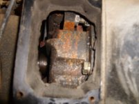
For the benefit of the OP: your TM432e clutch may differ slightly Mark's Jinma 200 series example, so here's a generic description of a 3 fingered Chinese tractor clutch train. From front to rear the sequence is
1. flywheel (which acts as one PTO pressure plate)
2. PTO friction disc
3. clutchpack (consisting of)
-PTO pressure plate
-PTO Belleville spring
-main drive pressure plate
-main drive friction disc
-main drive pressure plate 2
-main drive Belleville spring
-housing
-release fingers and associated hardware
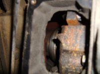
4. throwout bearing and bearing carrier
5. release fork

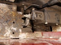
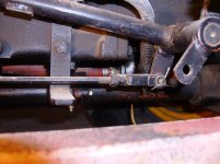
That's the end of the basic internals. Outside then is the
a. clutch release lever (connected to #5 above)
b. adjustable pull rod
c. clutch pedal

On the off chance you have a 6 finger clutch, let us know immediately - and I'll have to shift gears. They're laid out similarly, but have an entirely different adjustment technique.

//greg//
 
   / Best way to fix this???
  • Thread Starter
#14  
Hi, I attached a couple pics showing what I can see through the side of the bell housing. I'm not sure what it's supposed to look like, but there's not a whole lot of room to see anything. I checked the manual but all it says for the clutch is "2-late, dry type, constand meshing, operating independently double-acting clutch". The last pic I attached just shows the clutch where it goes back to the left side of the seat. Previous owner mentioned a little clutch trouble but said a friend of his fixed it up. That was 2 years ago and I haven't had any problems 'till now.
 

Attachments

  • HPIM9504.jpg
    HPIM9504.jpg
    372 KB · Views: 239
  • HPIM9505.jpg
    HPIM9505.jpg
    360.3 KB · Views: 214
  • HPIM9510.jpg
    HPIM9510.jpg
    754.9 KB · Views: 250
Last edited:
   / Best way to fix this??? #15  
Seems in the first photo that there's far far too much gap between the visible clutch release finger and the throwout bearing (not visible). That gap is typically no more than 2.5mm (+/- 0.5mm). That applies to all 3 fingers, so you have to rotate the clutchpack and inspect all 3 gaps. Again, not sure about the TM432e, but that gap is typically achieved by adjusting the external pull rod. When there's too much gap, you don't have enough pedal. Not enough pedal will make the PTO grind. But if all 3 gaps are different, that involves an internal adjustment as well.

Can't see anything of use in the 2nd photo. In it, the throwout bearing is visible - but the finger is not. And I'm not at all sure of what I'm lookin' at in the 3rd one.

//greg//
 
Last edited:
   / Best way to fix this??? #16  
Are you talking about the adjustment on the 3 rd pic ? That pic is of the left brake housing and brake adjustment ? On your clutch you need to take a better pic that includes the clutch finger and clutch release bearing in the same photo in order to see whats going on, it does look like the gap is big from the current pic.


Tommy
Affordable Tractor Sales
"Your Jinma Parts Superstore"
Home of compact Jinma, Foton, and Koyker Tractors and Parts, Wood Chippers, Backhoes - Affordable Tractor Sales Company
 
   / Best way to fix this???
  • Thread Starter
#17  
OK, I think I got a good picture here that shows the gap. FYI, it would appear there are 3 fingers, in my manual they are called Release Levers and it does show 3 of them. Secondly, I was wrong before when I said there was no room left for external adjustment. There is actually quite a bit as you can see in the second pic. What would you guys recommend for adjustment? Would doing it externally be enough or does that gap look to large and need to be adjusted as well?
 

Attachments

  • HPIM9520.jpg
    HPIM9520.jpg
    235.4 KB · Views: 216
  • HPIM9524.jpg
    HPIM9524.jpg
    539.2 KB · Views: 216
   / Best way to fix this??? #18  
The starting point is to get a set of feeler gauges and check all three finger-to-release bearing face gaps. Make sure they're all within 0.2mm of each other. The closer they are to absolutely equal, the better. Any that are out need to brought into spec or you'll just thrash the fingers in the long (or short) run. You'll need to lock the compression release open, pull the kill cable and lock it out, and turn the engine over with a wrench on the front pulley nut to check each finger gap. It takes some fiddling to get them all the same, back and forth until they're right, but it is necessary for proper clutch life.

Once the fingers are adjusted to the proper gap, then you can adjust the external pull rod to set the 2.5mm finger-to-bearing face gap and you should be in business.
 
   / Best way to fix this??? #19  
Three things;
1. it's clear that the two visible fingers are out of adjustment. All three should meet the 2.5mm spec (9+/-0.5mm) AND be within 0.1mm of each other.
2. finger wear. New fingers have ball tips, yours are flat. And not much of them left at that. Flat fingers are typically caused by (a) riding the clutch, and/or (b) incorrectly adjusted pull rod.
3. bearing wear. Excessive contact by the fingers prematurely ages the throwout bearing. Can't tell by the photo, but a telltale sign is blue discoloration.

Unless there's something wrong with the 3rd finger - and/or unless the TOB is blue - it may not be absolutely necessary to split the tractor at this particular time. But understand that they're not in good shape. Problem will be - without the proper ball end - you're gonna have trouble accurately adjusting the individual gaps to spec.

//greg//
 
   / Best way to fix this??? #20  
I agree, get the fingers adjusted then go to the pedal free play.

I did mine with a drill bit as a feeler gauge. Just found one that was 2.5mm and used it to be my feeler gauge. Its tough to get wrenches in there but its doable.

Chris
 

Tractor & Equipment Auctions

71066 (A49346)
71066 (A49346)
1996 PETERBILT 357 35 TON WRECKER (A50505)
1996 PETERBILT 357...
2015 JEEP Compass (A50324)
2015 JEEP Compass...
2012 John Deere 7280R MFWD Tractor (A51039)
2012 John Deere...
2000 Ford F650 Flatbed TMA (A49461)
2000 Ford F650...
2018 DODGE GRAND CARAVAN (A51222)
2018 DODGE GRAND...
 
Top