Update:
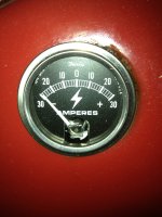
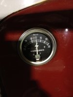
Full field test performed (field lead on the gennie grounded). Initially, the ammeter deflected sharply to the
negative. After two or three seconds, it deflected to the positive and rotated more to the right as I brought the RPMs up:

I shut the tractor off, pulled the ground jumper off the field post and then reattached the field lead. I turned the ignition key and the ammeter needle drifted slowly to the left as it usually does. I restarted the tractor and ran it at moderate RPMs and noticed the ammeter doing this:

That is certainly not normal. When I revved the engine, the needle drifted slightly right, but
never to the positive side. When I shut the engine off, I then noted this dreaded finding, again:

This (above) occurred with the engine off and the ignition key off. Once I pulled the power lead off the battery sparks flew and the ammeter looked like this again:

So it appears that something triggered by starting the tractor with the wires on the gennie in their current configuration causes the short.
Where do I go from here?
Why did the ammeter initially drift to the left (negative side) initially during the full field test before rotating to the positive side? What is the significance of this?
So far: gennie has been bench tested-OK
gennie has been "motored"-OK
gennie has been field tested-results shown above
new ammeter installed
new voltage regulator installed
wires between voltage regulator and genie have been continuity tested and
FLD on genie to FLD on vreg
ARM on genie to ARM on vreg
GROUND on genie to apparent GROUND on vreg (to bolt holding vreg to firewall)
final wire at vreg site attached to BAT on vreg.
I am stumped and frustrated. I can publish pics of the wiring on the genie and the subsequent wiring of the vreg if it will possibly be of value.
tmac


