Dump wagon build

   / Dump wagon build
  • Thread Starter
#61  
Thanks Aaron, that would be an option I hadn't considered.

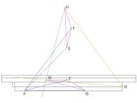
Spent the afternoon looking at scissor designs and playing with CAD and came up with the following. Please feel free to poke holes in it. This would reuse my existing 4x30 cyl and the existing lower cyl mount.

Point Legend:
A - Existing cyl base mount & scissor base mount
B - Scissor hinge pivot (lowered position)
C - Cyl/scissor mount (lowered position)
D - Scissor/bed mount (lowered position)
E - Scissor hinge pivot (raised position)
F - Cyl/scissor mount (raised position)
G - Scissor/bed mount (raised position)
H - Bed hinge

When the cyl A-C extends, it will be applying force on the B-C axis at 45 deg. This translates into a force of 19550 lbs at point C. This force will then try to rotate the BCD link around point B. As B-D = 2xB-C then force at point D would be 9775. This force is rotational around point B which is, in fact, a floating point moving in an arc from point B to E around point A. As point D raises, due to the floating pivot of point B and the fixed pivot of point H, D will move in a straight line to the fully raised point G. Line D-G is at 90 deg to Line DH therefore there would be 9775 lbs of lift at point D which would diminish as the box raises.

I don't know how to calculate lift force at anywhere higher than the fully down position but in reality, I guess it doesn't matter as the most lift is required at the bottom.

With 19550 of effective force at point C, where does the other 8150 of the 27,700 maximum push from the cyl go?

dump wagon scissor lift.jpg
 
   / Dump wagon build #62  
I have said for years that if I had it all to do over I would get a degree in engineering,now I know why I have one in economics instead.
 
   / Dump wagon build
  • Thread Starter
#63  
I have said for years that if I had it all to do over I would get a degree in engineering,now I know why I have one in economics instead.

Lol. I'm guessing you didn't follow then?
 
   / Dump wagon build #65  
... Spent the afternoon looking at scissor designs and playing with CAD and came up with the following. Please feel free to poke holes in it.
Ok ... your A-E line looks longer than your A-B line in the drawing ... is that in fact the case ?

Because that won't fly in the real world.

I don't know how to calculate lift force at anywhere higher than the fully down position but in reality, I guess it doesn't matter as the most lift is required at the bottom.
You need something like Solidworks ... which has a simulation module:

SOLIDWORKS Simulation | SOLIDWORKS

But yes, it's probably true that as long as you're good at the bottom of the lift cycle you'll be good the rest of the way - since the load should be decreasing and you will (or should) be gaining mechanical advantage.

With 19550 of effective force at point C, where does the other 8150 of the 27,700 maximum push from the cyl go?
Available (effective) force is dependent on the geometrical (is that a word ?) relationships of the various components in a system.

IOW, mechanical advantage (or disadvantage)

The cylinder isn't always capable of exerting 27,770 lbs of (effective) force - it is dependent on existing conditions - specifically only when certain relationships exist between the components being acted upon.
 
   / Dump wagon build
  • Thread Starter
#66  
I checked my drawing, line A-E = line A-B. Must be just an illusion. The only line that length changes is A-C to represent the cyl extension.

I thought a hyd cyl would always have the same amount of force available based on the surface area of the piston and the input pressure. Where and how that force is distributed is dependent on the relationship of the components. Am I wrong?
 
   / Dump wagon build #67  
I checked my drawing, line A-E = line A-B. Must be just an illusion. The only line that length changes is A-C to represent the cyl extension.
Good.

I thought a hyd cyl would always have the same amount of force available based on the surface area of the piston and the input pressure.
True - that's why I said "effective" previously.

Where and how that force is distributed is dependent on the relationship of the components. Am I wrong?
No ... but you're (kinda) answering your own previous question ... ;)
 
   / Dump wagon build
  • Thread Starter
#68  
Effective, in this case would mean "doing what I'm trying to do"? IOW, how much of the force is actually doing the lift. The remainder of the force still has to go somewhere.

In my current (poorly designed) setup, I've got about 5000 lbs of lift and 22700 lbs trying to push the bed horizontally off the back. As we all agree, not an ideal situation.

So would that not mean that in this scissor lift with 19500 of lift at point C, the other 8200 goes ???? Just guessing here but into the hinge of the scissor and then down to the lower pivot to point A?

If so, would this be a tension or compressive load on the lower link? Depending on which way I think about it I get either or both. Seems to me that during lift the hinge would be the fulcrum of the upper link puting the lower link in compression but in a stationary raised position, point C would be the fulcrum which would put the lower link in tension. This doesn't make sense as for this to be true, at some point the force on the lower link would have to be zero.


Just trying to understand and learn how all this works so that when I rebuild this I size components accordingly and only have to do it once (more)

I appreciate all the help.
 
   / Dump wagon build #69  
In my current (poorly designed) setup, I've got about 5000 lbs of lift and 22700 lbs trying to push the bed horizontally off the back.

And the cylinder is pushing equally as hard on the base mount trying to move it down and forward.

Bruce
 
   / Dump wagon build #70  
Effective, in this case would mean "doing what I'm trying to do"? IOW, how much of the force is actually doing the lift. The remainder of the force still has to go somewhere.

In my current (poorly designed) setup, I've got about 5000 lbs of lift and 22700 lbs trying to push the bed horizontally off the back. As we all agree, not an ideal situation.

So would that not mean that in this scissor lift with 19500 of lift at point C, the other 8200 goes ???? Just guessing here but into the hinge of the scissor and then down to the lower pivot to point A?

If so, would this be a tension or compressive load on the lower link? Depending on which way I think about it I get either or both. Seems to me that during lift the hinge would be the fulcrum of the upper link puting the lower link in compression but in a stationary raised position, point C would be the fulcrum which would put the lower link in tension. This doesn't make sense as for this to be true, at some point the force on the lower link would have to be zero.


Just trying to understand and learn how all this works so that when I rebuild this I size components accordingly and only have to do it once (more)

I appreciate all the help.
You are now into the engineering world of 'statics'. It's actually not that difficult but it is all about 'freebody' diagraming. Static Forces must be equal and opposing. As long as the joint is statically determinate you can calculate the loads. Say you have three members, if you know one of the members, you can calculate the other two based on their relative angles to each other. Break up your force into x and y components and then figure what the other x,y components must be based on their angles. You can do this with a little algebra or maybe look online for a free or cheap statics program for trusses, etc. Been too long for me but it does bring back memories. I wonder if I could still pass a college test? :ashamed:
 

Tractor & Equipment Auctions

2016 LT63 Towable Light Tower (A51691)
2016 LT63 Towable...
2014 Ford Escape SE, Eco Boost (A52384)
2014 Ford Escape...
2010 Ford Edge SE SUV (A51694)
2010 Ford Edge SE...
2012 CATERPILLAR 279C2 SKID STEER (A51246)
2012 CATERPILLAR...
FIRESTONE 420/85R30 TIRES WITH 8 LUG WHEEL - WHEEL FITS TM SERIES NEW HOLLAND (A52748)
FIRESTONE...
IMPORTANT PLEASE READ!!!! TERMS AND CONDITIONS (A51573)
IMPORTANT PLEASE...
 
Top