Building my bridge crane

   / Building my bridge crane #1  

LD1

Epic Contributor
Joined
Apr 30, 2008
Messages
22,822
Location
Central Ohio
Tractor
Kubota MX5100
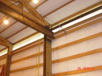
though I'd post some pictures of the 37' bridge crane that I have been working on.

I got a bunch of beams for a really good price. The main beam is W18x60 and I got 2 25' sections. I need the beam to be 38' long, so....cut 13' off one beam and weld to the 25' section of the other.

IMG_20151115_142430165_HDR.jpgIMG_20151115_155414894_HDR.jpgIMG_20151117_115201833.jpgIMG_20151117_121334287.jpgIMG_20151117_121344471_HDR.jpgIMG_20151117_121400982.jpg
 
   / Building my bridge crane
  • Thread Starter
#2  
This shows a better angle of the beam size

IMG_20151116_184850439.jpg
 
   / Building my bridge crane
  • Thread Starter
#3  
Next up is the end trucks. I already had 2 crane wheels 8" diameter and double flange. They are expensive to buy. I had a piece of pipe 8" od and 6" Id so I decided to make 2 more wheels.

Used a 3/8" plate for the flange, roughed in with the plasma, then cleaned up on the lathe.
 

Attachments

  • IMG_20151118_234621269.jpg
    IMG_20151118_234621269.jpg
    335.5 KB · Views: 541
  • IMG_20151118_192529126.jpg
    IMG_20151118_192529126.jpg
    249.4 KB · Views: 431
  • IMG_20151117_225648807.jpg
    IMG_20151117_225648807.jpg
    364.1 KB · Views: 380
  • IMG_20151117_212416274.jpg
    IMG_20151117_212416274.jpg
    364.1 KB · Views: 448
   / Building my bridge crane
  • Thread Starter
#4  
Once one flange was on, and everything turned true, I added the other flange. If I would have put both flanges on from the start, wouldnt have had a way to hold it in the lathe to true up.

Then bored out the flange plates to accept a piece of ~3.625" OD heavy wall pipe, that I counterbored for the bearings.

IMG_20151119_210651523.jpgIMG_20151120_011708171.jpg
 
   / Building my bridge crane
  • Thread Starter
#5  
TO mount the wheels, I didnt have exactaly what I wanted but made it work. MC6x12 channel for the ends with 3/8" plates, all attached to 6x6x1/4" tube. Hard to describe, will let pics do the talking.

IMG_20151121_133348603.jpgIMG_20151121_195056257.jpgIMG_20151121_195228560.jpgIMG_20151121_204523622.jpg
 
   / Building my bridge crane
  • Thread Starter
#6  
Thats as far as I have gotten. I will post more pictures as I begin to "erect" the structure
 
   / Building my bridge crane #8  
I'm very interested in seeing how you mount the truck beams.
 
   / Building my bridge crane #9  
LD1, you do your homework and do good work, but please be sure to look into the effects of welding a patch in like that. I am not concerned with the patch or the welds (assuming they were done right, which is likely) but you are introducing a pretty significant non-uniformity/non-linearity into the beam with a joint, patch, and weld within the span. The upshot is that simple beam calculations/tables (and any factor of safety you thought you had based on them) go out the door. Factor of safety is only valid when the beam is consistent with the assumptions in the calculations. When it's not, the factor of safety is void.

Look at it this way -- the beam equations are based on the slopes and curvatures of the beam under flexural loading. There are assumptions about continuity. I think I touched on the calculus aspect of it in the other thread. When you increase the stiffness mid-span with a patch and welds, that is no longer a single continuous beam with continuous slopes and curvatures. You will end up with a stiffer flat spot at the patch and that makes it a different problem entirely.
 
   / Building my bridge crane #10  
S219
If you look at any bridge that has been repaired , there are non uniform areas. Most bridge beams start out non uniform if you look at bracing and stiffeners installed.
As long as LD does a good job welding, which it appears he is, he is nor causing significant problems. Stiffer areas will pull some load from the weaker areas.
 
   / Building my bridge crane
  • Thread Starter
#11  
I am no pro at any of this. But I am not concerned.

I will rate the W18x60 beam over the 37' span for 5k max load.

That is WELL under the failure point of the beam. I assigned this value based on many many crane beam span tables I have looked at.

Assuming 36ksi yeild steel (A36) which is the weakest beam because most are actually A992 (50ksi), A 5:1 Safety factor based on stress is 7013lbs.

And the plating is not right in the middle either. The spliced pieces were 13 and 25', so that puts it in a lower stress area.

I figured the plating wasnt even necessary. Everything was beveled all the way through and welded with 100% penetration. I just figured the plating wouldnt hurt and I had the material anyway.

Shieldarc:

The truck beams are 20' long and going to set on columns 15' apart. The columns are W10x33 beams with a 12x12x1/2" plate and (4) 3/4" anchors to the floor. On top is a 8x"x10"x1/2" plate welded. The truck beams are going to sit on top and be welded all the way around.

The truck beams are slightly different sizes. One is a W8x24 and the other is a W8x31. Same height though and both strong enough for the span.

Then there will be knee braces going from the column to the truck beam. Havent decided yet if I will add a few braces to tie into the wall or not. The columns are 10' high and feel pretty darn solid.
 
   / Building my bridge crane #12  
The engineer who helped me with my bridge crane, said to tie the crane to the building where ever I could. He also kept emphasizing to build a box. He suggested these pipes that go between the crane rails.
 

Attachments

  • Connection.jpg
    Connection.jpg
    40.1 KB · Views: 637
  • Cross pipe.jpg
    Cross pipe.jpg
    43.3 KB · Views: 761
   / Building my bridge crane
  • Thread Starter
#13  
Got the rails just sitting atop the columns now. I think I will tie it into the building. 10'+ leverage on the anchors in the floor....

No way to do any sort of ties between the rails on mine with a too-runner. And given the 37' span I am not sure what good they would do. They would sag under their own weight
 
   / Building my bridge crane
  • Thread Starter
#14  
Here are the rails. They are just sitting up there now, still have to weld. And there will be 3 knee braces. 2' down the column and 2' out the beam. pretty self explanatory where they will go. Will eventually get another 5' of rail for each side to make the rail the full 20' length of the side beams.

IMG_20151123_135151964.jpgIMG_20151123_135204248.jpg
 
   / Building my bridge crane #15  
Your splice plate should not have pointed ends in my opinion. The points create stress concentration which could cause higher stress at the points leading to fractures.

A bolted splice plate would be more suitable if needed. Of course one piece beam is preferred.

Google splice plate for I beam... You'll get some good images of what I'm referring too.
 
   / Building my bridge crane #16  
Never seen a fish plate bolted onto an excavator boom. And they see more dynamic loading than a span beam for a bridge crane. ;)
 
   / Building my bridge crane #17  
Your splice plate should not have pointed ends in my opinion. The points create stress concentration which could cause higher stress at the points leading to fractures.

A bolted splice plate would be more suitable if needed. Of course one piece beam is preferred.

Google splice plate for I beam... You'll get some good images of what I'm referring too.
WRONG! ... The tapered ends act to blend the stiffness from the beam into the stiffer area of the patch. Also the taper away from the edges of the flange inhibit a tear/crack beginning at the edge of the flange.

,,, Bolting is a bad idea in comparison to a good weld. Many stress riser sharp edges are inherent in drilling holes, and are difficult to blend out to alleviate cracking. ... Also you lose the strength of the material removed from the holes.
larry
 
   / Building my bridge crane #18  
That is gonna be one **** of a shop LD1. What uses are you planning on doing in there.
 
   / Building my bridge crane #19  
WRONG! ... The tapered ends act to blend the stiffness from the beam into the stiffer area of the patch. Also the taper away from the edges of the flange inhibit a tear/crack beginning at the edge of the flange.

,,, Bolting is a bad idea in comparison to a good weld. Many stress riser sharp edges are inherent in drilling holes, and are difficult to blend out to alleviate cracking. ... Also you lose the strength of the material removed from the holes.
larry
I agree with the first half of your statement. The weld is correct in this situation. I have used similar welded splices in the past

Bolted and welded connection are useful in different situations. Neither connection is better than the other for all situations.
Bolted connections are a common way to repair cracks in bridge beams.
I have seen many cracked welds in bridges, the only bolted connections that I have seen cracked also had large amounts of section loss from rust.
 
Last edited:
   / Building my bridge crane
  • Thread Starter
#20  
Your splice plate should not have pointed ends in my opinion. The points create stress concentration which could cause higher stress at the points leading to fractures.

A bolted splice plate would be more suitable if needed. Of course one piece beam is preferred.

Google splice plate for I beam... You'll get some good images of what I'm referring too.

Wouldnt really call it a point. Its rounded. Looks just like every other plate I have seen.

That is gonna be one **** of a shop LD1. What uses are you planning on doing in there.

Already done lots of stuff in there. But just in general all the crap that I post about here. Building my logsplitter, re-furbishing implements, restoring tractors, maintaining vehicles and equipent, etc.

First on the list is yanking the motor out of the backhoe for a rebuild. Crane will be nice for that, as a standard cherry picker is gonna be about worthless on the ford 5500
 

Tractor & Equipment Auctions

2016 CATERPILLAR M322F MOBILE EXCAVATOR (A60429)
2016 CATERPILLAR...
2013 ORTEQ ENERGY GN182 GOOSENECK HOSE TRAILER (A58214)
2013 ORTEQ ENERGY...
2006 Ford F-750 Fuel and Lube Truck (A59230)
2006 Ford F-750...
9ft. Flatbed Truck Body with Gooseneck Connection (A59230)
9ft. Flatbed Truck...
2012 Ram 2500 4x4 Crew Cab Pickup Truck (A59230)
2012 Ram 2500 4x4...
2014 RAM 2500 (INOPERABLE) (A58214)
2014 RAM 2500...
 
Top