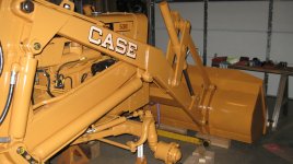
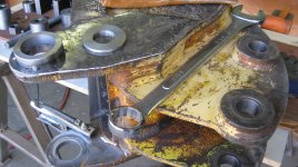
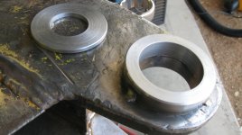
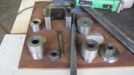
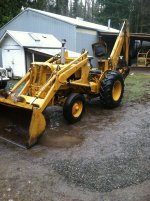
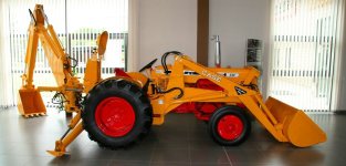
OK Andy, here are a few pictures of the main hydraulic lines to and from the spool valve box on the backhoe and tractor:
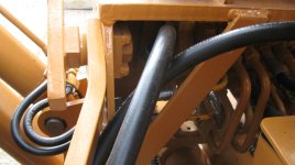
Both lines are, high pressure and are 5/8" ID. I believe. In this picture, the line that is crossing underneath is the line and attaches on the right side of the spool valve box and feeds the hoe with fresh hydraulic fluid, and the line that is coming straight back in the picture and attaches to the left side of the spool valve box, is the return line to the filter, then to the reservoir. To help orient yourself to my pictures, this is looking rearward toward the hoe. Also, remember that both lines coming from the spool valve box have quick coupler fittings (the line supplying fluid should be a female and the return line should have a male coupling on the end of it) , and the reason for this is: when you remove the hoe and use only the tractor loader, this allowed the hydraulic system on both hoe and loader to be isolated from contaminates and still operable as well as loosing, and wasting fluid. Remember, these 530CK's were being marketed to more than construction companies; which would leave the loader/hoe as a unit and were being sold to landscapers, yard handler. farmers, etc.
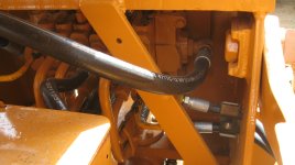
Looking rearward, but the right side is the feed line and of course is clearer than the other side because there is nothing in the way, easier to access too.
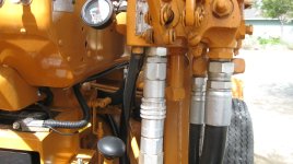
OK, in this shot you can see where the feeder line (with quick coupler center)is attached to the loader spool valve box. It is the line that is all metal in the picture. The main line that feeds both loader and hoe is the largest on the right and 1" ID., it comes directly from the hydraulic pump in the front of the engine.
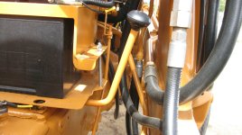
I included this one to show you the large 1" line as it transitions from hard tube to flexible hose (on the right). The line, lower left, (the return hose) going to the filter that has a female fitting on the lower end of it, that when detached would then hook up to where the hose that you see in the center is. This would now allow the hoe to be removed and only the loader would be functional. I know it looks smaller than the hose going up to the valve box, front and center, but it is the same size.
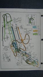
Here is the parts picture that I color coded for my purposes, it helped me visualize all of the connections and hoses, there are so many and it is confusing if you are not doing this for a living. I labeled all of the hard tubes and color coded them to keep them straight. If you right click each one of these pictures as you peruse them, then save them to your computer, you can then blow them up and magnify for clearer viewing.
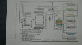
This is the breakdown of the whole hydraulic system: loader and hoe, again, save this picture to your computer then use whatever picture device you have and study it in a larger format. Hope this helps and if you have any more questions, I'll be glad to help if I can, Stan.
