Three point electrical control problems on Branson 6530C

   / Three point electrical control problems on Branson 6530C
  • Thread Starter
#11  
Hi Mark
I have scanned the electrical sections of the service manual.
Only problem the way I scanned it, the pages are not all in the same direction.
If you print it out, single sided you should be ok.
Also note that the sheet size is A4 I think, so you will need to scale to fit standard letter size.
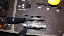
Also here is a photo of the plastic panel with the 3 point arm control levels and the third empty slot.
I haven't tested the relay removal yet, still working to finish off my hay, which if all goes well, I will be done first cut this weekend.
Douglas


Branson 6530 levels.jpg
 

Attachments

  • Chapter 6 electrical Branson 6530C.pdf
    9.2 MB · Views: 505
   / Three point electrical control problems on Branson 6530C #12  
Hi Mark
I have scanned the electrical sections of the service manual.
Only problem the way I scanned it, the pages are not all in the same direction.
If you print it out, single sided you should be ok.
Also note that the sheet size is A4 I think, so you will need to scale to fit standard letter size.
Also here is a photo of the plastic panel with the 3 point arm control levels and the third empty slot.
I haven't tested the relay removal yet, still working to finish off my hay, which if all goes well, I will be done first cut this weekend.
Douglas


View attachment 561272

The slot is for a sliding, knurled nut operated, lock for setting the lower limit for the position control. I never used it because if you slammed the control too hard it would move. The one outside rear is bullet proof and it's probably missing because the PO agreed with me and took it off.....good riddance.

I have my manual on my desk here in the house. Just tell me the page/item ID and I'll follow your questions.
 
   / Three point electrical control problems on Branson 6530C
  • Thread Starter
#13  
Hi Mark
Thanks for that information.
I will start to look at the diagrams and make a short list of questions, but most likely that will not be until mid next week, still working at the hay here and until I get that done with, I have limited time to park the tractor and get it ready to start the debugging process. Looking forward to finding out what the issue/fault is and fixing it.
Have a great weekend.
Douglas
 
   / Three point electrical control problems on Branson 6530C #14  
Hi Mark
Thanks for that information.
I will start to look at the diagrams and make a short list of questions, but most likely that will not be until mid next week, still working at the hay here and until I get that done with, I have limited time to park the tractor and get it ready to start the debugging process. Looking forward to finding out what the issue/fault is and fixing it.
Have a great weekend.
Douglas

I'll keep an eye out.
 
   / Three point electrical control problems on Branson 6530C
  • Thread Starter
#15  
Hi Mark
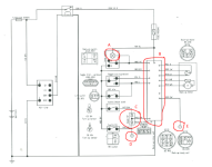
Here is the page of the wiring diagram for the back up control of the three point hitch.
I have circled in Red five items which apply to the questions below.
A-does the light on the switch come on only when the back up is turned on?
B-what is this block and where is it located?
C-any idea of where I should look for this diode assembly
D & E what do these letters indicate, other then the continuation of the wiring, do they tell me somewhere else to look?

I am going to pull the seat out over the next few days, as I understand I will have better access to the up/down motor and wiring from a panel under the seat.

I wonder if there is some sort of wire damage etc, like a short, as the 3 point hitch lamp in the dash cluster is on all the time and it seems to look like if a wire was grounded it might be the cause for that.

And other suggestions.
back up wiring drawing.PNG

Thanks
Douglas
 
   / Three point electrical control problems on Branson 6530C #16  
Hi Mark
Here is the page of the wiring diagram for the back up control of the three point hitch.
I have circled in Red five items which apply to the questions below.
A-does the light on the switch come on only when the back up is turned on?
B-what is this block and where is it located?
C-any idea of where I should look for this diode assembly
D & E what do these letters indicate, other then the continuation of the wiring, do they tell me somewhere else to look?

I am going to pull the seat out over the next few days, as I understand I will have better access to the up/down motor and wiring from a panel under the seat.

I wonder if there is some sort of wire damage etc, like a short, as the 3 point hitch lamp in the dash cluster is on all the time and it seems to look like if a wire was grounded it might be the cause for that.

And other suggestions.
View attachment 561851

Thanks
Douglas

I have the Branson badged, high back air seat. To get it out I tilt it back as far as it will go and pass it out thrugh the rear window. Goes out quite easily.

A pinched wire is always a possibility.
A rat ate through the insulation at the wrong place is also a possibility.

The relay is a central point but relays are "traffic cops" of a sort: You have 2 or 3 contacts so you either have ON-OFF control or you have direction control...common to circuit A or common to circuit B. You could have 20 "sets" of contacts in one relay and none of them are related other than when the relay changes positions, all of them change position.

The above is why I don't think the relay alone is the culprit unless it had a catastrophic failure where a contact mounting within the relay broke and the contact fell on an ill intended circuit.....but that wouldn't be several ckts.

I'm busy right now but I'll look at it later today. Meanwhile you dig around and see if you have any rat poop around, first thing to consider when they visit....or nesting material, or little piles of junk (pack rat....had one recently).
 
   / Three point electrical control problems on Branson 6530C
  • Thread Starter
#17  
Hi Mark
I started at it last night, removed the seat to get to more controls as well as opened up the right plastic cover to get to the up/down switch etc.
What I know for sure now.
The up/down switch is good, contacts open as close when they should.
Lift switch, at the left upper link arm is also good.
The item B in the diagram turns out to be a circuit board located in a plastic housing under the seat floor. So I opened it up as well, and didn't see anything out of place, ie burnt traces, discolour components etc. Does mean it is good, but without more skills, I will not know.
The push button for the auto lift is working somewhat, it is a little weak so I have called the dealer to get a price on a replacement.
I will test the front axle turn switch tonight, and also power up the system and start to see where I find voltage and where I don't. The system seems to show that the up/down switch control should still work if the relay control board is acting up, but testing will hopefully tell me more.
As for mice/rat damage, I have had to deal with that in a past life, but I had a good look at the machine and have not seen any evidence of mice damage, however a pinched wire is still possible from simple wear and tear.
Will start tracing voltage tonight and see what that shows.
Hopefully I don’t set my tractor on fire.
:laughing:
Douglas
 
   / Three point electrical control problems on Branson 6530C #18  
I printed off your progress thus far and am going over it.
 
   / Three point electrical control problems on Branson 6530C
  • Thread Starter
#19  
Hi Mark
Had some better luck this evening.
I now have the UP/Down switch working and controlling the three point hitch.
But still do not have the auto lift function working.
I do think I found one of the problems, but am not 100 percent sure.
It seems that the back up motor connector is the same size as one of the connectors on the back up relay box and I think someone had them connected wrong, as after i had everything apart, i was confused myself as to what plug where, so using the wire colours worked it out. After that the Up/Down switch now controlled the back up motor, which in turn controlled the three point hitch.
However the auto up system is not right.
If i have the links in the down position and the auto lift off, as soon as i turn the auto lift one the arms will raise. I can them put them down with the up/down switch.
However after that, no turning of the front wheels or putting the tractor into reverse will cause the arms to lift like the system should. Also I believe that the control PCB is also part of the auto off PTO system and I don't have that working either.
I am going to work as the front axle switch tomorrow to see if it is working, and also try and test the forward/reverse switch as well to make sure they are working correctly.
Looking at the drawings, i should find 12 volts to one side of that front switch when the auto up is on, correct?
Thanks
Douglas
 
   / Three point electrical control problems on Branson 6530C #20  
"I have circled in Red five items which apply to the questions below."

I corrected my response today from what I submitted yesterday. I better understand that the "Backup Relay Unit" is a separate assembly with an A and B connector. Shouldn't be all that hard to find.....see below for guesses as to where it is.

In answering your above questions:

A-does the light on the switch come on only when the back up is turned on? Yes.

B-what is this block and where is it located? Correction from yesterday after looking closer today: It's identified as the "Backup Relay Unit" and has 2 connectors, one larger than the other. Page 6-25 where you circled the what is it.......has the two connectors' pinouts with wire color codes, below and to the right of the thing you circled. They also show up on Page 6-28 at the bottom, identified as the backup controller A connector, with the pinout for troubleshooting, and on Page 6-29 at the top. These two charts may tell the story you are looking for as to is this relay functional or damaged in some way. Where is it located???? I'd guess somewhere in the wiring of the control console to the right of the seat. Second guess would be under the steering/instrument panel console where the brake shuttle connectors are or behind the instrument panel in that shroud that encircles it.


C-any idea of where I should look for this diode assembly? Correction from yesterday: May be part of the "Backup Relay Unit". Both diode assys, appear to be "inductive spike" clamping diodes protecting the contacts of the relay. Otherwise they are steering diodes for the different functional paths associated with 12v.....like when one function is being used, they allow it to be used but prevent it from interfering with another function not being used.

D & E what do these letters indicate, other then the continuation of the wiring, do they tell me somewhere else to look? D, aka your red Circled B is on page 6-30, Section F, Horn & Lamp Circuit...diagram, upper right area of schematic, provides ground to the "backup light relay" when you push the backup automatic button above the up down toggle switch.

E is on page 6-20, Section D. Warning Circuit, Diagram near the bottom, right of center. When it closes via the relay mentioned above, it turns on the dash "3 pt raised" amber lamp.
----------------------

The sections of this manual pretty much lead you through each component at the connector and tell you how to trouble shoot it. What's missing is understanding the whole scenario since things are wired in series and....... this has to happen for that to happen or if that happens this will.......

The motor: First of all it's a slave component. It gets told what to do. It can be tested as shown and if not satisfied, I'd put 12 v across it and run it one way (just long enough to see it respond) and reverse the leads and run it the other. The enclosed relay symbol may be a built in limit switch on the motor to shut it off when it hits a limit to prevent motor burnout. That switch could be bad, but it and a bad motor have no bearing on your dash lamp remaining illuminated since it gets illuminated on the "move command", not on the results of where the "move command" told the motor to move.........."Person of interest" Relay popping up again.

If all that works, then I'd replace the relay in the "Backup Relay Unit".......apparently it's not one of the relays in the relay panel, above the engine, behind the fuse panel.

Most relays have part numbers on them and are www traceable. If it's plug in it's a no brainer. If soldered, I think you have shown me your electrical expertise so that shouldn't be a problem for you either.
Things are pointing toward the relay in the "Backup Relay Unit" and the reason is 3 key points of activity are wired through it and since they all don't work, the common denominator is the relay.

I think I typed what I think I understand. Keep me posted.

Mark
 
Last edited:

Tractor & Equipment Auctions

2017 Ford F-550 Ext. Cab Valve Maintenance Truck (A50323)
2017 Ford F-550...
2003 Big Tex 10PI 16ft. T/A Pipe Top Utility Trailer (A49461)
2003 Big Tex 10PI...
Komatsu WA270-8 Articulated Wheel Loader (A49346)
Komatsu WA270-8...
2008 CATERPILLAR 320D L (A50854)
2008 CATERPILLAR...
30ft Pole S/A Towable Trailer (A49346)
30ft Pole S/A...
2009 HINO 185 18FT BOX TRUCK (A51219)
2009 HINO 185 18FT...
 
Top