b2910 flasher/hazard fuse shorting out

   / b2910 flasher/hazard fuse shorting out #11  
not sure about your meter continuity setting, this could be the ohm setting, your explanation sounds like it is. the ohm emblem looks like an upside down U with legs coming out of each of the bottom lines. Your readings does imply that there could be a short in the positive wire. Ohms is the measure of the amount of resistance. when you test the wires you MUST have all electrical devises disconnected or it will measure the resistance of those devises like the bulbs. DO NOT have any power on the wire you are testing, that could damage your meter. I have never owned or worked on a Kubota so I cannot help with how to get under the dash.
 
   / b2910 flasher/hazard fuse shorting out #12  
We're here to coach ya along here! ask all the Q's ya want! All good. So. to knock this one around a bit more. I like the test you have described above and we need the numbers and if you can, a Pic of the meter and the number if ya can? Else just record the number. (Ohms usually has a multiplier range and can be .automatic on the meter, or part of where you switch too...and ya never know.. so a pic for me say's it all).

OK, you are putting a lead on the Gw to gnd and Rw to gnd. ( PS is Ground in your test the frame or battery gnd btw?). Let's get the numbers.


Once we sort out your Meter and whats what: Here is a thought. See if this makes sense.
A thought (see what the dog thinks here too). The failing fuse line, for current flow on your lights, is a long wire cut in half (for example) w/ a fuse in the middle. If the current exceeds the flow in that long wire... pop!
SO, you have the fuse out now. Try 1 meter lead on one of the fuse holder blades and then 1 to ground. Then you can try 1 meter lead on the other fuse blade holder (other side) and then test to ground.
This can show if the half of the wire on the left is shorted... or if the half on the right is shorted. trying to see if we can help ya eliminate and isolate.

We'll get it yet! I'll try to look at the print in the manual I sent ya the link too tomorrow early over coffee.

From your Q:
So If I am understanding this correctly, both positive wires going to my lights are grounding out somewhere.
My answer (IMO) Possibly. Depends on the number on the ohm meter.
Example of why we need to see it: (google search on what continuity really means for different ohm ranges is below) What this is noting below is that w/o us seeing the number we really cannot tell you if it's shorted to ground or just part of the normal ohms that should be there. Not uncommon to see a meter on + from a LED or light bulb's + wire to ground be a few hundred ohms or more. We 'limit' current to the bulb with a resister at times to limit current shock and longevity of the bulbs. does that help or hinder?


What does continuity mean on an Ohm meter?
Featured snippet from the web
If the range is set to 400.0 Ω, a multimeter typically beeps if the component has a resistance of 40 Ω or less. If the range is set 4.000 kΩ, a multimeter typically beeps if the component has a resistance of 200 Ω or less.


Thank you all for the responses. Let me try to be more clear on what I have tried. I don't know that much about electrical, ohms, etc.

What think I understand is that the positive Gw (Green white) and Rw wires going to the lights should show no continuity to ground when not plugged into the light sockets.

I have the lights removed, they work fine on their own. The fuse is removed. When I use the turn signal, the flasher clicks in both directions.

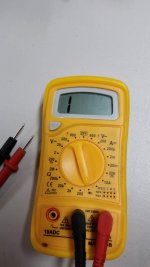
I am using a small electric meter set to the continuity setting, it sort of looks like this (->|). The meter reads '1' when the leads are not together. When they are together, the number changes; I have not taken note of the numbers when testing the wires but will the next time. I put the + lead on the Gw wire, and the - lead to ground, the number on the meter changes which I assume means there is continuity. I also do it with the B (black) wire coming to each side and the number changes because that is ground to ground. I do the same on the other side with the Rw wire and the number changes as well.

So If I am understanding this correctly, both positive wires going to my lights are grounding out somewhere.

If I need to look anything under the dash, how to I get it open?
 
Last edited:
   / b2910 flasher/hazard fuse shorting out #13  
Maybe this tutorial link below can help ya a bit. I love the sparkfun folks. From your post, the indicator symbol is often the Diode and/or combo Diode & continuity mode. (see URL and pic on the meter in that tutorial).
I think Ohm is the easier of the two. Tell me the brand and model of your meter. I'll find a google image and tell ya where to put the knob. or pop me a PM and we can sort out a few things there.

How to Use a Multimeter - learn.sparkfun.com


For Ohms (resistance) just a few selections up on that same tutorial.
How to Use a Multimeter - learn.sparkfun.com
 
   / b2910 flasher/hazard fuse shorting out
  • Thread Starter
#14  
Maybe this tutorial link below can help ya a bit. I love the sparkfun folks. From your post, the indicator symbol is often the Diode and/or combo Diode & continuity mode. (see URL and pic on the meter in that tutorial).
I think Ohm is the easier of the two. Tell me the brand and model of your meter. I'll find a google image and tell ya where to put the knob. or pop me a PM and we can sort out a few things there.

How to Use a Multimeter - learn.sparkfun.com


For Ohms (resistance) just a few selections up on that same tutorial.
How to Use a Multimeter - learn.sparkfun.com


Thanks for hanging with me on this. I will try to get some pictures tomorrow.
 
   / b2910 flasher/hazard fuse shorting out #15  
Maybe this tutorial link below can help ya a bit. I love the sparkfun folks. From your post, the indicator symbol is often the Diode and/or combo Diode & continuity mode. (see URL and pic on the meter in that tutorial).
I think Ohm is the easier of the two. Tell me the brand and model of your meter. I'll find a google image and tell ya where to put the knob. or pop me a PM and we can sort out a few things there.

How to Use a Multimeter - learn.sparkfun.com


For Ohms (resistance) just a few selections up on that same tutorial.
How to Use a Multimeter - learn.sparkfun.com

Sparkfun headquarters is 15 min from my house! I love the place ;)
 
   / b2910 flasher/hazard fuse shorting out
  • Thread Starter
#16  
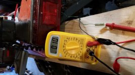
Here is a pict of the meter set to continuity.
no continuity .jpg

Here with the leads crossed
continuity .jpg

Left side Gw wire to frame ground
Left Gw to frame gnd.jpg

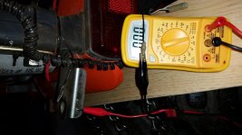
Left Gw to B gnd wire
left Gw to gnd wire.jpg

Left Gnd to gnd
left gnd to gnd.jpg

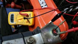
Right side Rw to frame ground

Right Rw to frame gnd.jpg

Right side frame ground to to B gnd wire
right grnd to grnd.jpg


Countryguy, I was confused by the following
Once we sort out your Meter and whats what: Here is a thought. See if this makes sense.
A thought (see what the dog thinks here too). The failing fuse line, for current flow on your lights, is a long wire cut in half (for example) w/ a fuse in the middle. If the current exceeds the flow in that long wire... pop!
SO, you have the fuse out now. Try 1 meter lead on one of the fuse holder blades and then 1 to ground. Then you can try 1 meter lead on the other fuse blade holder (other side) and then test to ground.
This can show if the half of the wire on the left is shorted... or if the half on the right is shorted. trying to see if we can help ya eliminate and isolate
 
   / b2910 flasher/hazard fuse shorting out #17  
Dave, OK, your Meter is definitely on "DIODE" check which passes a small current thru the device and then reports back based on a voltage drop back when I did this stuff. Now, I used to do all this 2 decades ago. So maybe someone else will note if that check is OK or not but...
if you do not mind: I would prefer you turn your Meter knob to the "Ohms 200" setting. 1 click CW (clock wise) Then retry those same tests. No need for the pics. Just report the numbers back w/ the same headings from the pic.

And if you have the time, could you add two small tests? Do the fuse blade (where the fuse plugs in). Red lead on the blade. black lead on the frame. (on the left or top side). And then repeat for the fuse holder right or bottom side) Hope you see where I'm going /w this? back to that long wire analogy and which side of the fuse (from the print I'll know) might be the short to ground. Or, I going to smack my forehead and go duh.. but I think it's in my head that it'll help us. 2min test I think.

All in all - It certainly appears to report that you have 0 ohms gnd to gnd. 10 to 11 ohms from the two Gw and and Rw lines. Let me go check the print and see which is which there and what's what.


Last meeting today is 2:30. I'll pull the print and report back by the late PM for ya.
 
   / b2910 flasher/hazard fuse shorting out #18  
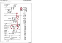
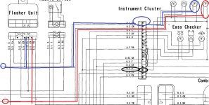
So. In the manual stating on page 337, I pulled some images. As you can see by my Red and blue marks, there is a lot of wiring. As noted in one of the first posts; I've also seen this in equipment as a few scenarios. Rubbed bare to ground, speared to grounding , melted, other conductive (corrosion and other), and then someone's modifications.

From what I can tell, you need to start unplugging things. From the Flasher unit, to the big connector where these all go together and figure out if you can say ... it's shorted on this side... but not that side. Sorry I cannot be more help here but I think your going to be pulling connectors and possibly getting under the hazard dash /console setup.

Some high level notes and pics:

There are two 20am fuses noted in the diagrams. Is yours blowing on the RED wire or the RED/YELLOW wire. The print shows two. the Red is part of the Battery feed and makes sense since if you were stalled and needed hazards they run off the battery.

As you can see from the images, IMO there is essentially 4 areas you get to trace out. And the best way is to start unplugging connectors and then trying the Rw and Gw colors any place you find them on the connectors.

My thoughts....IMO on what I'd be yanking and checking. This includes taking my cutters and cutting and then re-splicing and then heat/shrink + taping back together. The objective here is to find where she's shoring . 20A to me is the 10-11 ohms which will blow it every time.

you get to really dig in now IMO but others may have some better ideas too.


1) The Harness and local wiring the travels the back.
2) the long haul from back ends to the console and fuse assy.
3) The instrument cluster and whats underneath.
4) Flasher unit and wiring. Where is that? part of 1, 2, or 3. Probably under the hood?

B2910OverallElec.jpg

taillight-toEasyChecker1.jpg

taillightMain1.jpg
 
   / b2910 flasher/hazard fuse shorting out
  • Thread Starter
#19  
Dave, OK, your Meter is definitely on "DIODE" check which passes a small current thru the device and then reports back based on a voltage drop back when I did this stuff. Now, I used to do all this 2 decades ago. So maybe someone else will note if that check is OK or not but...
if you do not mind: I would prefer you turn your Meter knob to the "Ohms 200" setting. 1 click CW (clock wise) Then retry those same tests. No need for the pics. Just report the numbers back w/ the same headings from the pic.

And if you have the time, could you add two small tests? Do the fuse blade (where the fuse plugs in). Red lead on the blade. black lead on the frame. (on the left or top side). And then repeat for the fuse holder right or bottom side) Hope you see where I'm going /w this? back to that long wire analogy and which side of the fuse (from the print I'll know) might be the short to ground. Or, I going to smack my forehead and go duh.. but I think it's in my head that it'll help us. 2min test I think.

All in all - It certainly appears to report that you have 0 ohms gnd to gnd. 10 to 11 ohms from the two Gw and and Rw lines. Let me go check the print and see which is which there and what's what.


Last meeting today is 2:30. I'll pull the print and report back by the late PM for ya.

Ohm meter set at 200

Right side
Rw to B wire = 11.1
Rw to frame = 11.4
B to frame = .9

Left side
Gw to B wire = 11.1
Gw to frame = 11.4
B to frame = .9

With negative clipped to frame
Left side of fuse = 80
Right side of fuse = 1
 
   / b2910 flasher/hazard fuse shorting out
  • Thread Starter
#20  
Thanks for highlighting those electric diagrams. I'll have to figure out how to remove the instrument cluster. If this gets much more complicated, I'll just hang a blinking LED from my rops when I need it. :)
 

Tractor & Equipment Auctions

2004 International 4300 Truck, VIN # 1HTMMAAMX4H667102 (A44391)
2004 International...
More info coming soon! (A44572)
More info coming...
2011 FREIGHTLINER M2 (A45046)
2011 FREIGHTLINER...
LOCATIONS OF ASSETS SOLD (A43004)
LOCATIONS OF...
New 5ft Bush Hog Rotary Cutter (A44391)
New 5ft Bush Hog...
PTO Driven Winch (A44391)
PTO Driven Winch...
 
Top