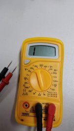
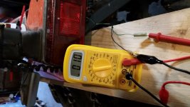
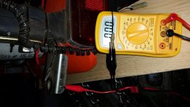
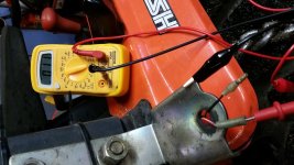
We're here to coach ya along here! ask all the Q's ya want! All good. So. to knock this one around a bit more. I like the test you have described above and we need the numbers and if you can, a Pic of the meter and the number if ya can? Else just record the number. (Ohms usually has a multiplier range and can be .automatic on the meter, or part of where you switch too...and ya never know.. so a pic for me say's it all).
OK, you are putting a lead on the Gw to gnd and Rw to gnd. ( PS is Ground in your test the frame or battery gnd btw?). Let's get the numbers.
Once we sort out your Meter and whats what: Here is a thought. See if this makes sense.
A thought (see what the dog thinks here too). The failing fuse line, for current flow on your lights, is a long wire cut in half (for example) w/ a fuse in the middle. If the current exceeds the flow in that long wire... pop!
SO, you have the fuse out now. Try 1 meter lead on one of the fuse holder blades and then 1 to ground. Then you can try 1 meter lead on the other fuse blade holder (other side) and then test to ground.
This can show if the half of the wire on the left is shorted... or if the half on the right is shorted. trying to see if we can help ya eliminate and isolate.
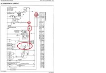
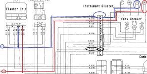
We'll get it yet! I'll try to look at the print in the manual I sent ya the link too tomorrow early over coffee.
From your Q:
So If I am understanding this correctly, both positive wires going to my lights are grounding out somewhere.
My answer (IMO) Possibly. Depends on the number on the ohm meter.
Example of why we need to see it: (google search on what continuity really means for different ohm ranges is below) What this is noting below is that w/o us seeing the number we really cannot tell you if it's shorted to ground or just part of the normal ohms that should be there. Not uncommon to see a meter on + from a LED or light bulb's + wire to ground be a few hundred ohms or more. We 'limit' current to the bulb with a resister at times to limit current shock and longevity of the bulbs. does that help or hinder?
What does continuity mean on an Ohm meter?
Featured snippet from the web
If the range is set to 400.0 Ω, a multimeter typically beeps if the component has a resistance of 40 Ω or less. If the range is set 4.000 kΩ, a multimeter typically beeps if the component has a resistance of 200 Ω or less.
Thank you all for the responses. Let me try to be more clear on what I have tried. I don't know that much about electrical, ohms, etc.
What think I understand is that the positive Gw (Green white) and Rw wires going to the lights should show no continuity to ground when not plugged into the light sockets.
I have the lights removed, they work fine on their own. The fuse is removed. When I use the turn signal, the flasher clicks in both directions.
I am using a small electric meter set to the continuity setting, it sort of looks like this (->|). The meter reads '1' when the leads are not together. When they are together, the number changes; I have not taken note of the numbers when testing the wires but will the next time. I put the + lead on the Gw wire, and the - lead to ground, the number on the meter changes which I assume means there is continuity. I also do it with the B (black) wire coming to each side and the number changes because that is ground to ground. I do the same on the other side with the Rw wire and the number changes as well.
So If I am understanding this correctly, both positive wires going to my lights are grounding out somewhere.
If I need to look anything under the dash, how to I get it open?
