OP
2515R Dude
Platinum Member
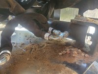
It is a simple "T". In my opinion it does as i described. From the front of one cylinder the oil under the pressure escaped directly to the back of another cylinder and does not go to the tank. And as i see it, if there is air trapped inside, it will never escape and be play a role of a cushion till it pressurized enough till is able to transfer the pressure.BTW, I believe that the diagram you posted disagrees with the description of how you describe the flow in #2 above. It is hard to be 100% sure without a flow or schematic diagram - and without more details about the T part BY400-8800111.....but if it is a simple T....then the way I see it, that diagram doesn't show that the oil coming out of one cyinder goes to the other cylinder to help in the movement. That's good. It would be odd if it did.
Is there any way i can check if there is air inside the cylinder?
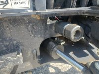
I dont see how it goes to the sump. but again, i dont have any experienceMy guess is that in each extension direction the combined expelled flow from the cylinders is returned back through the valve to the sump without any regeneration. Take another look and see what you think.
rScotty