Ballast Centre of Gravity

   / Ballast Centre of Gravity #41  
This is not entirely correct, as the term 'power' is being incorrectly substituted for 'rotational input speed'. Power is the rate at which work is done, and in the context of a tire the same amount of power can be delivered by a small tire (lower torque with higher speed) as a large tire (higher torque and lower speed).

There is no standard definition of 4x4 vs 4WD (4-Wheel-Drive) vs MFWD (Mechanical-Front-Wheel-Drive; primarily used by John Deere) vs FWA (Front-Wheel-Assist). FWA originally referred to the ability for the front wheels to be hydraulically driven to assist when additional traction was needed, and the driving speed was not linked to the rear tires in any way. In general, 4x4, 4WD, and MFWD are all used to refer to drive systems in which the front and rear tires are mechanically coupled (a locked center differential, or no differential at all) to produce approximately the same travel speed (not necessarily the same wheel speed).

"Lead/Lag" refers to the difference in speed between the front and rear tires. Most systems are designed with 2-4% front wheel lead because when turning the front tires travel farther than the rear tires, so a slight lead helps minimize binding in the drive train. (There is also a benefit to having the front pulling versus the rear pushing when traveling in a straight line) For a simple example, our tractor will have rear tires with a circumference of 4 and front tires with a circumference of 2. As part of the drive train the manufacture will gear the tractor differential so that the front tires spin 2.1 times the speed of the rear tires. This means each time the rear tire makes one revolution and travels a distance of 4, the front tires will have made 2.1 revolutions and traveled a distance of 4.2 (a 5% greater distance).

AWD (All-Wheel-Drive) refers to systems that have a center differential that allows the front and rear tires to turn at different speeds instead of being locked together. This allows the systems to be used on pavement and other hard surfaces without creating binding and excessive wear. AWD is primarily used in passenger vehicles, and I am unaware of any tractors that have an AWD system.

You seem to miss the point of my statement that it was much more involved than what I presented. As well as my remarks about highway vehicles when I mentioned AWD.

So the conclusion is you have reading comprehension issues at a minimum!
 
   / Ballast Centre of Gravity #42  
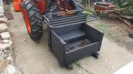
I decided to build a small carry-all box out of the Tractor Supply Co. frame. Wanted good maneuverability in tight spots (box blades and rotary cutters stick out too far either way) Had the extra wood laying around, and very lucky to have a friend that gave me 7-800 lbs of old window weights.

They are around 20lb each. I loaded the bottom of the box with them, roughly 400 lb... nice because it's low, and then just have a couple hundred lb of chains and tools in there too. I figure plus the weight of the box itself I'm around 600 lb. total which seems nice for most things given my loader/tractor capacity.

I can always just take the weights out or add more by hand. I have plenty extra :)

Still need to finish mounting the storage rack on top but you get the idea this is a multi-use counterweight that I hope works out for me...yet to be tested.

Didn't really cost too much, a little over $200 for the frame plus hardware??
20200926_103532.jpg
20200926_103519.jpg
20200926_095510.jpg
 
   / Ballast Centre of Gravity #43  
Use a rear lift forks to move the totes, put some weight in the bucket. Why would you want to stress the front axle with that much weight, especially on rough surfaces ?

have to agree. if the op is mostly moving totes the rear forks would be much easier in the tractor. The loader isnt (on a tractor) really designed for rough use.
I have my tires loaded. I can max my lift on flat ground and keep the rear tires on the ground without any ballast on the 3 point.
 
   / Ballast Centre of Gravity
  • Thread Starter
#44  
Thanks for all the interesting and useful responses.
Before posting my original question, I had already bought the steel and pins, and drilled all the holes, with the intention of making a ballast block.
3-Point pallet forks are a great idea but would cost me just a bit north of $2,000. Nothing is cheap in Australia!
With this in mind, I have decided to proceed with building the ballast block, which will require just under $400 worth concrete.

If the earth was flat, one could have the bottom of the block at a level where it touched the ground when the lower arms are at their lowest point. In reality, we need to have the base of the block lower so that, when the block is resting on the ground, the arms are not at their lowest point. How much leeway space should I allow?
 
   / Ballast Centre of Gravity
  • Thread Starter
#45  
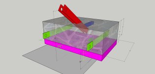
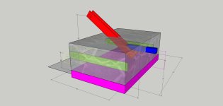
I have made a Sketchup drawing of my initial plans for the ballast.

At their lowest point, the lower arms on my tractor have the centres of the holes 5" above the ground. I have extended the base of the block down another 4" (depicted in pink on the drawings) so that the arms are not at their lowest point when the block is on the ground.

The upper linkage (red in the drawing) is positioned so that the upper arm will be about 1" (maybe a bit more) clear of the PTO cowling when the block is at its lowest position.

Ignore the position of the receiver (blue in the drawing) - I'll adjust this once I have finalised the main dimensions.

One of my main goals with this design, perhaps totally foolishly, was to get the centre of gravity very low. I think this design achieves that, but at the expense of extending back possibly a bit further than is ideal.

With these dimensions the block will end up weighing around 2,400 lbs (1,083kg). The tractor is a Kubota MX 5100, so this block might be too heavy for the tractor. Perhaps I should cut off the two corners farthest from the tractor, to reduce the weight and to improve the maneuverability.

Is there a rule of thumb formula for an approximate target ballast weight e.g X% of the Rear-lift capacity at 24" ?

All comments and suggestions about this design would be greatly appreciated. Bear in mind that I have about 35-40 hours of experience on the tractor, so I am definitely open to all advice you can give about the design.

Ballast block CAT-2  INCHES 01.jpgBallast block CAT-2  INCHES 02.jpg
 
Last edited:
   / Ballast Centre of Gravity #46  
I have made a Sketchup drawing of my initial plans for the ballast.

At their lowest point, the lower arms on my tractor have the centres of the holes 5" above the ground. I have extended the base of the block down another 4" (depicted in pink on the drawings) so that the arms are not at their lowest point when the block is on the ground.

The upper linkage (red in the drawing) is positioned so that the upper arm will be about 1" (maybe a bit more) clear of the PTO cowling when the block is at its lowest position.

Ignore the position of the receiver (blue in the drawing) - I'll adjust this once I have finalised the main dimensions.

One of my main goals with this design, perhaps totally foolishly, was to get the centre of gravity very low. I think this design achieves that, but at the expense of extending back possibly a bit further than is ideal.

With these dimensions the block will end up weighing around 2,400 lbs (1,083kg). The tractor is a Kubota MX 5100, so this block might be too heavy for the tractor. Perhaps I should cut off the two corners farthest from the tractor, to reduce the weight and to improve the maneuverability.

Is there a rule of thumb formula for an approximate target ballast weight e.g X% of the Rear-lift capacity at 24" ?

All comments and suggestions about this design would be greatly appreciated. Bear in mind that I have about 35-40 hours of experience on the tractor, so I am definitely open to all advice you can give about the design.

View attachment 671164View attachment 671163
I screwed 1"x4"x16" boards in the bottom of the forms. Once the concrete set, I removed the boards, leaving 1x4 sockets. Then I pounded in 2x4 boards that protrude 1" below below the ballast and act as feet so it is a bit easier on the garage floor. This would allow you to adjust your pin height.
As for weight, I have found that 50% of the loader capacity is not quite enough and I even have loaded tires. If I was to do it again I would go 2/3s. As mentioned above, the pressure relief valve should activate before the rears come off the ground, but that is hard to determine.
My local ready-mix concrete place filled my forms for free...well, a donation to the coffee fund. I took them them the forms screwed to a pallet and they loaded it on my trailer once filled. Getting it off was the tricky part.
 
   / Ballast Centre of Gravity
  • Thread Starter
#47  
I screwed 1"x4"x16" boards in the bottom of the forms. Once the concrete set, I removed the boards, leaving 1x4 sockets. Then I pounded in 2x4 boards that protrude 1" below below the ballast and act as feet so it is a bit easier on the garage floor. This would allow you to adjust your pin height.

Neat idea!


As for weight, I have found that 50% of the loader capacity is not quite enough and I even have loaded tires. If I was to do it again I would go 2/3s.

The specs for the loader differ depending on the distance from the pivot pin. It looks like 1,400kg would be a realistic number. My tractor is spec'd for a rear lift of 1,050kg at 24"/610mm from the ends. 2/3 of 1,400kg would be 933kg. That is seems to me to be pretty close to the limit of 1,050kg, but perhaps I am being too conservative.

It looks like the weak link in my setup is the capacity of the rear lift, and the calculations would need to be based on this limitation and not on the loader capacity. Would 800kg sound about right for my situation?
 
   / Ballast Centre of Gravity #48  
The further out from the 3pt lift arm pins the greater the effect as a counter balance to the loader. This is why 3pt weight is more effective vs loaded tires. The dimensions look reasonable for a low center of gravity and safe counterweight that's small in size.
 
   / Ballast Centre of Gravity #49  
You seem to miss the point of my statement that it was much more involved than what I presented. As well as my remarks about highway vehicles when I mentioned AWD.

So the conclusion is you have reading comprehension issues at a minimum!
Rancher Ed had a much more correct description of 4wd then you did or have.
Any 4wd system that mechanically ties the front to rear axles together will have different gear ratios for each axle if they have different tire sizes,
both axles will receive the same amount of power.
FWA was originally used to differentiate between hydraulically assisted front axles from mechanically driven front axles;
This is an assist system on an Oliver; http://www.hartparroliver.org/albums/2006dovershepva/100_1161.jpg
And here is a 4wd one; http://www.tractorshed.com/gallery/tphotos/a21994.jpg
And here is a 4wd that went a completely different route for power distribution http://www.tractordata.com/photos/F000/222/222-td3b.jpg
 
   / Ballast Centre of Gravity #50  
Neat idea!


The specs for the loader differ depending on the distance from the pivot pin. It looks like 1,400kg would be a realistic number. My tractor is spec'd for a rear lift of 1,050kg at 24"/610mm from the ends. 2/3 of 1,400kg would be 933kg. That is seems to me to be pretty close to the limit of 1,050kg, but perhaps I am being too conservative.

It looks like the weak link in my setup is the capacity of the rear lift, and the calculations would need to be based on this limitation and not on the loader capacity. Would 800kg sound about right for my situation?

Interesting ratio. I am no expert - just sharing my one experience. If I was in your situation I would likely settle on 800kg. It will dramatically improve safety when lifting heavy loads. You may not be able to safely lift 1400kg, but how often do you need to. You will love how much safer your tractor feels every time you raise the counterweight.
 
 
Top