Boom pole geometry

   / Boom pole geometry #1  

Jim_W

Member
Joined
Mar 24, 2002
Messages
38
Tractor
1952 Ferguson TEA20, 1951 Ferguson TEA20
Is there anyone who has made this and can report on how well it works? I have scrounged some steel and am trying to find out the best geometry for not lifting too fast vs. getting enough height - as I intend to use it to install/remove engines, among other things, and want fine control.
I assume the one in this diagram pivots where the triangle meets the beam. Others I have seen for sale must require a top link - if I go with a solid unit how short does the top link need to be?
Thanks,
Jim
PS Category one, Ferguson TEA20, only interested in 3 point, no FEL.

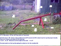
PPS whoops blew it on the attachment, meant to provide link instead: Boom pole plan .
 
   / Boom pole geometry #2  
That link refuses to connect for me.
 
   / Boom pole geometry #4  
Also, you need to have Active-X enabled on the computer, otherwise Acrobat won't show anything.
 
   / Boom pole geometry #5  
How fast the end of the boom moves depends on the motion ratio, which you probably already know. I did some quick math and came up with a 101/33 motion ratio, or roughly 3:1. In other words, when the 3ph eyes move upwards 1 inch, the end of the boom should move three inches. This is a rough calculations, but should be relatively accurate. How fast do you want the end of the pole to move, realtive to the 3ph? Twice as fast? Half as fast?

To make the boom move slower, the motion ratio needs to be lower. The simplest way to make the ratio lower is to make the boom shorter at the 46" or 28" dimensions. Leave the 26" and 20" dimensions as is, since they need to fit your 3ph. I'd just make the boom pole per the drawing, then add a whole bunch of places to attach the hook between the end of the pole, and the attachment point at the 46" mark. That way your boom pole has different settings for load and motion ratios, depending on where you hang the load. Alternatively, I'd just use the boom pole as is, leave it in the full up position, and hang a chain hoist on the end to pull engines with.

The other way is with a shorter top link as you said. As the boom pole is raised by the 3ph, the longer 3ph links would rotate through a smaller angle than the shorter top link for the same linear displacement. That would force the end of the pole to move at a different rate than the fixed 3ph version. This geometry gets a little complex, and motion ratios are dependant on the geometry of the actual 3ph mounts on the tractor. If the top link could vary in length (pretty easy to accomplish), then the motion ratios could be controlled by the top link length. Also, for very fine resolution, you could just crank the top link manually with a wrench or something (weld a hex nut on it).

I've never built this, these are just my thoughts.
 
   / Boom pole geometry #6  
Jim,

Sometimes its helpful to make a simple articulated paper model of a linkage like this to see if the motion is in a useful range and if you can vary the lengths to get what you want. Make scaled down links, including your tractor 3ph geometry, out of index card stock and assemble them using thumb tacks as pivot points. (We're just looking at the side view here). Run the lower 3ph link thru its range of motion and watch the what the tip does.

John
 
   / Boom pole geometry #7  
If I were using this for removing and reinstalling engines, I would want to incorporate into the design a winch mechanism for fine control of raising and lowering. The tractor hydraulics are not going to give you the finesse that is needed to align an engine to a transmission. I assume that you are aware of the engine lifting device that bolts to the block that allows you to change the angle of tilt by turning a sprocket. I don't remember what they are called, but I know that I have one from my old days turning wrenches. A life saver as opposed to just a chain bolted to the engine.
 
   / Boom pole geometry
  • Thread Starter
#8  
Junkman,
Good call! I hadn't thought of that; in my mind's eye the transmission and engine were going in to the car as a unit but of course that's not necessarily always true.
I should therefore have the tip of the pole high enough to make room for the tilt-a-chain thing (I know what you mean).
Thanks,
Jim
 
   / Boom pole geometry
  • Thread Starter
#9  
Aardvark, jmc,
Between your two posts I think I can make some progress, thanks.
For some reason I like the idea of a solid unit (easier to make maybe), which implies a top link, but couldn't wrap my mind around figuring out the length of the top link.
I will go off and play with some models. That should inspire some confidence.
Jim
 
   / Boom pole geometry #10  
I believe that the tilt-a-chain thing you are referring to is a load leveler. Look here . /forums/images/graemlins/smile.gif
 

Tractor & Equipment Auctions

4- 6 DRILL COLLARS (A50854)
4- 6 DRILL COLLARS...
2010 John Deere Gator UTV (A49461)
2010 John Deere...
2022 Club Car Tempo Golf Cart (A48082)
2022 Club Car...
2012 Honda Civic LX Sedan (A50860)
2012 Honda Civic...
1984 Trailmobile Enclosed Van Trailer (A51039)
1984 Trailmobile...
2014 Brent 1596T Dual Auger Grain Cart (A50657)
2014 Brent 1596T...
 
Top