BobRip said:
Yes, there should be a wire on each side of the "thermal relay"
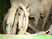
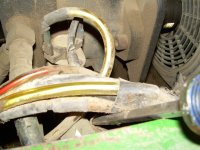
The missing wire goes into the wiring harness. See attach pictures for it's location. It comes out of the wiring harness right next to the scewdriver that I am using to hold the wiring harness in view and away from the side.
Yes, you can jumper those wires together and make the fan run whenever the key is on. You can run it from the white wire. My guess is that the lug has broken off of the white wire.
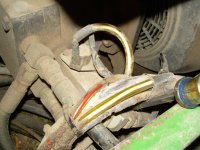
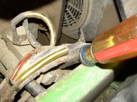
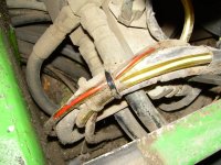
The white wire is in a clear plastic tube (which I might have installed, but I don't think so). The wire runs from where the screw driver is, forward and then undeneath the wiring harness and over to the "thermal relay".
You could run your own wire through the tunnel and up to the ignition switch if you cannot find the existing on.
If you have a meter you can check the wire. If there is voltage on it when the key is on and no voltage when the key is off, then it is probably the right one.
The "thermal relay" is a temperature switch which I belive cuts on at 130 deg F. I believe it is commonly used in clothes dryers. I have replaced mine once.
Bob, Carl, and Bill,
First let me thank each of you (and any others if I missed your name) for taking the time to respond...and with so much good and valuble info.
Carl...I will have to read your post on wiring the relay a couple times, to understand it. It is not you, but me, takes awhile to sink in.
Bill...I appreciate the info on the 'SO #14-5', I thought that was the wire gauge and number of wires, but it would have taken some time to figure out or search the "SO" part.
Bob...yes, that is exactly the setup! My white wire going back to the harness is also in a clear rubber tube, but it does not have the right connector to fit on the other side of the relay. It has a different type than the push on spade that is from the fan (with the fuse).
{I am definitely going to be calling that service center I used, it almost seems deliberate. If the connector broke from the wire, the push on spade connector should still be on the male fitting of the relay, and the white wire would show a break, not a different connector.}
After talking with Carl the last time, I went out and checked the relay using the ohm meter, and it is working like it should be when hot & cold.
I then checked to see if the white wire in the clear rubber tube was hot with the ignition key on...it was.
Then I took a nail and put in the connector on the white wire and touched the push on spade from the fan with the fuse, and the fan came on...so fan is good.
So, I am thinking I will change the connect on the white wire to a push on spade and put onto the other side of the thermal relay.
-------------------------------------
Does anyone see a problem with this?
-------------------------------------
(It seems to be the way the diagram shows, and it is the set up that Bob has also, except for the fuse on the fan side.)
Carl...should I still put the relay in?
Bob...do you have a fuse on the fan side?
Let me again stress to all how much I appreciate the help, pics, suggestions, and comments. "PT guys" are...well they are "PT guys"! I think that says it all.