Electricians: can neutral be anything but white?

   / Electricians: can neutral be anything but white? #131  
Looking forward to your tests.

Running a mwbc with shared neutral is no different than the power coming to your box from the meter/xfmr. (2)/120v legs with ONE neutral.

That neutral will NEVER see more current than what is one ONE single leg. It is NOT additive.

In fact, the service entrance can have a downsized neutral in most cases. And the only way to overload it would be to pull the max off a single leg and NONE from the other. Which would be very unlikely. It don't matter if you pull 10 amps from each leg, or 200 from each leg. If what you are pulling is equal, amps on neutral will be zero. If its not equal, neutral only sees the difference

I'm beginning to think you're not quite as dumb about electricity as the title of your post implies!:D BTW, the next time I'm in the mood to get 150 replies and 1,600 views on a post I'll put "electrical" in the title. I'll set up the test in the morning and I'll also rig an oscilloscope to see what noise might be inducted from a sparky drill to the other leg, but I formally admit that I was wrong about overloading the neutral. The test should bear this out.
 
   / Electricians: can neutral be anything but white?
  • Thread Starter
#132  
IF you have an o-scope, I am curious to see if a shared neutral induces any more noise than a standard circuit.
 
   / Electricians: can neutral be anything but white? #133  
Yes I have a handheld scope and will probly just use a clamp meter for the load test. Not sure of the max load my ammeters can handle, but if I have one rated at 10 amps I'll splice it in. I don't think noise will be significant and the only tool I would be cautious with using in such an arrangement is my TIG which I occasionally use with the 110 adapter. Well, maybe my vintage 1975 Craftsman radial arm saw too since it was such a pita to rewind the stator by hand. I baby that saw now and even give it a little push when I start the thing.;)
 
   / Electricians: can neutral be anything but white? #134  
People talking about modern electronics as them being more sensitive to voltage spikes is for most part a fable, most of them use switching power supplies convert to DC and run on that. Computers laptops TVs etc pretty much all of them do now a days if it is digital it is 95% of time running this way. These devices are actually more generators of junky power than worried about it seeing "noisy" power coming in. Look at most of these small power supplies for phone chargers or laptops they are rated 90~240vac input and then run out 5 to 30vdc depending on what part of the circuit ya look at. Often a +/- supplies with all sorts of different power/voltage points of use internal to them.

As for people saying they have 2 lines 180 out of "phase" that is true for most residential power but again not a 100% true statement as lots of areas run 3phase down the road and tap a leg to leg single phase transformer & depending on the version then they may only be 120 degrees out of phase. That means 208v not the traditional 240v & is common in 3phase 240/208 industrial applications (more rare in residential but happens.) Some cases you will have a "High Leg" to neutral in industrial places.


Speaking of which I have worked places wired by color blind people and ones that were put in when Edison was still alive. I have seen pipe fitting used as fuses, fused neutrals pennies in fuse panels & green wires used as hots more than I care to say... Seen a row of 12ea 277v wired brand new high bay lights be blown up when a neutral came apart in a 4 square box so know what shared neutrals can & do when some comes apart.

What was said about using a shared neutral (as above) notes when the shared neutral splits everything plugged into those lines SHARE the voltage between the power phases some that are lower resistance passes higher current & blow up and higher resistance devices pass less current so operate weak also failing due to under voltage.

It is fine under most conditions perfectly safe this is what the power company does coming into every single phase home...

m
Mark
 
   / Electricians: can neutral be anything but white? #135  
What was said about using a shared neutral (as above) notes when the shared neutral splits everything plugged into those lines SHARE the voltage between the power phases some that are lower resistance passes higher current & blow up and higher resistance devices pass less current so operate weak also failing due to under voltage.

It is fine under most conditions perfectly safe this is what the power company does coming into every single phase home...

m
Mark
The hi resistance leg operates at hi V. The lo resistance operates at lo V. With open neutral the loads go into a series connection condition so both legs carry the same current. E[lectromotive Force] = IR
 
   / Electricians: can neutral be anything but white? #136  
E=IR is not just a good idea, it is the law! Ohm's law!:)
 
   / Electricians: can neutral be anything but white? #137  
The hi resistance leg operates at hi V. The lo resistance operates at lo V. With open neutral the loads go into a series connection condition so both legs carry the same current. E[lectromotive Force] = IR

you are correct, my wording and being up too late caused a mental speech/type impediment.. What I SHOULD have said is that "respective devices current" changes vs its "Rated Current" at it's specified voltage.

a 25 watt light bulb on one leg and a 100 watt bulb on the other leg with open (shared) neutral has 240Volts across the combined Resistance. Knowing the wattage of normal circuit using P=IE (Power/Wattage)=Current*Voltage.

A 100Watt Bulb on 120V line the "Normal" current is 100W/120V=0.83amps.
A 25watt bulb normal current would be 25W/120V=0.208A.

The "Combined Wattage" would be 125W with a combined 240V across them, so 125W/240V=0.521 Amps (Combined Series Amperage.)

As you see the "Combined Current" is HIGHER in the (low wattage device) and Lower in the "Higher Wattage" device. This situation is BAD for BOTH devices the smaller bulb will burn bright & soon burn out which leaves the 100W bulb dim and running on low voltage. If they are ONLY devices on at that time they BOTH go out when the 25watt bulb burns out as the 100watt bulb no longer has a complete circuit.

M
 
   / Electricians: can neutral be anything but white? #138  
you are correct, my wording and being up too late caused a mental speech/type impediment.. What I SHOULD have said is that "respective devices current" changes vs its "Rated Current" at it's specified voltage.

a 25 watt light bulb on one leg and a 100 watt bulb on the other leg with open (shared) neutral has 240Volts across the combined Resistance. Knowing the wattage of normal circuit using P=IE (Power/Wattage)=Current*Voltage.

A 100Watt Bulb on 120V line the "Normal" current is 100W/120V=0.83amps.
A 25watt bulb normal current would be 25W/120V=0.208A.

The "Combined Wattage" would be 125W with a combined 240V across them, so 125W/240V=0.521 Amps (Combined Series Amperage.)

As you see the "Combined Current" is HIGHER in the (low wattage device) and Lower in the "Higher Wattage" device. This situation is BAD for BOTH devices the smaller bulb will burn bright & soon burn out which leaves the 100W bulb dim and running on low voltage. If they are ONLY devices on at that time they BOTH go out when the 25watt bulb burns out as the 100watt bulb no longer has a complete circuit.

M
Yes. Good show of the concept. I dont know how to get an exact handle on it - probably only empirically since,
due to the extreme change in filament resistance during thermal runaway the combined wattage will be an approximation and thus also the combined series Amp. All we know is that doubling the voltage will not double the current in an incandescent light. ... Edit: This is a characteristic that comes in handy to provide positive operation on a relay while sparing cumulative thermal load on its coil. A bulb in series provides hi pull in current that very quickly tapers to a lower holding current
larry
 
Last edited:
   / Electricians: can neutral be anything but white? #139  
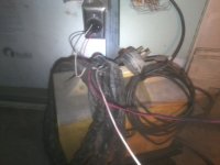
OK, for simplicity I set this up using the 220v outlet used by the plasma cutter:
1.jpg

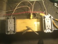
Please excuse the crudity of this model. I didn't have time to build it to scale or paint it:
01.jpg

Voltage reading across the two hots in the 110v duplex outlets= 238v:
03.jpg

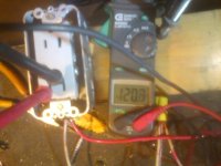
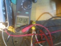
No load voltage across 110v outlet on red side= 120.7v:
03.jpg

No load voltage across 110v outlet on black side= 121.2v:
04.jpg

Camera battery died whilst performing the clamp meter amperage test, but the results were as LD1 had predicted; i.e. using two identical Lasko box fans, the neutral measured .5 amps with one fan on high speed. The hot side for that fan measured .5A as well. The idle hot measured 0.0 amps. When both fans were on the neutral measured 0.0A to .01A and both hots measured .5a respectively.

I will perform and photograph the noise tests in the morning. Been a long day, good night.
 
   / Electricians: can neutral be anything but white? #140  
Back on page 7 I said I had my mind made up. But never said which way I was going to go (intentionally). I am not gonna be doing a MWBC. I would only be saving basically 1 run of wire around the shop. While I would save 2 wires in theory, thats only to the first outlet, which is only 3 feet from the main. Then I would have to add a neutral for that GFI circuit. With all the circuits being GFI, everytime I start a new circuit, I add a ground. So only saving what is equal to 1 run of wire, and risk of 240v, I am going to do a typical install.

I think your decision is the best way in your situation (which is very similar to my situations). You really save very little and it causes a couple annoyances, and potential for mixups down the road with shared neutrals, especially in your case.

One more thing I would suggest. I like to skip-wire outlets in a shop. I run 2 circuits at the same time (separate cables) but pick off opposing circuits for every outlet. Then i color code the outlets using white for one, ivory for the other (for example). So outlets next to each other are on different circuits. If you need to plug in a dust collector or vacuum and also use a heavy draw tool, you often will trip a single 20A circuit, so this helps you spread it out without a bunch of extension cords. There are other examples where you need 2 things running that will exceed one circuit, so this makes it a bit easier to avoid nuisance trips. Not critical, but I think it makes things nicer.
 

Tractor & Equipment Auctions

2021 Case IH Magnum 240AFS CVX Connect MFWD Tractor (A50657)
2021 Case IH...
Craftsman T1800 42in. Riding Mower (A49346)
Craftsman T1800...
GENERATOR HOUSE POEWERED BY TWIN 12.7 DETROITS (A50854)
GENERATOR HOUSE...
Kubota 24in Quick Attach Compact Excavator Tooth Bucket ONE PER LOT (A51039)
Kubota 24in Quick...
2004 Big Tex 10PI 16ft. T/A Pipe Top Utility Trailer (A49461)
2004 Big Tex 10PI...
2021 CATERPILLAR 953 CRAWLER LOADER (A51242)
2021 CATERPILLAR...
 
Top