Gear Driven Hydraulic Scarifier System on Boxblade

   / Gear Driven Hydraulic Scarifier System on Boxblade #1  

3RRL

Super Member
Joined
Oct 20, 2005
Messages
6,931
Location
Foothills of the Giant Sequoia's, California
Tractor
55HP 4WD KAMA 554 and 4 x 4 Jinma 284
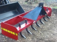
I converted my 7' Howse Boxblade during my vacation so that it now has a hydraulic system to raise and lower the scarifiers. I got the idea from other threads I read here and figured it would be a fun project.

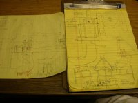
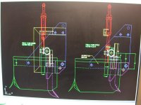
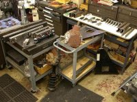
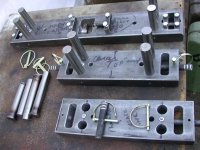
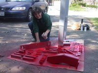
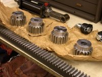
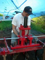
I'll show a lot of pictures (again) to show the new "look" first and then the process of changing it. This project took quite a lot of machining and a little design work to retro-fit everything so it would work properly. Lucky, I was able to do most of the component machining in my shop at home, but much of the welding, fitting and final assembly had to be done at my rural property. My biggest concern was the proper line up of all the leader pin guides, the gears, shaft and racks. I had no way to fixture or bore holes at the property to guarantee perfect association between them.

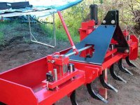
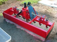
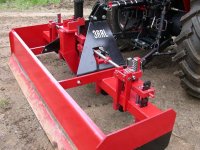
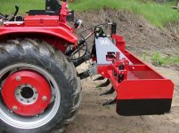
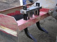
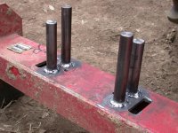
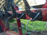
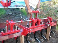
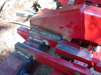
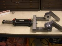
Here is the first picture of the finished hydraulic system on the boxblade. Notice the handle to move the system manually in the event of a blown hose or cylinder. The handle screws off the end that stays on the shaft and I'll store it in one of the tool boxes on the tractor. All components and gears are keyed to the shaft. Notice the pins that guide the scarifier lift blocks up and down. Also notice that each gear/rack assembly is enclosed to keep the appropriate pitch diameter relationship. Also the clearance through the large black brackets for the system to work.

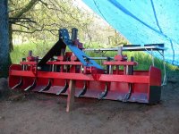
I also added supports for the lift pins now that the boxblade nears 1,000 lbs in weight. And finally supports around the sides and back of each scarifier to add strength and reduce bending and breaking.
 

Attachments

  • 867951-BOXBLADE ASSEMBLED SHOWING MANUEL  LIFT HANDLE.JPG
    867951-BOXBLADE ASSEMBLED SHOWING MANUEL LIFT HANDLE.JPG
    94.5 KB · Views: 2,568
   / Gear Driven Hydraulic Scarifier System on Boxblade
  • Thread Starter
#2  
This is a picture from the rear that shows each of the gear/rack assemblies and the center mount that supports the hydraulic cylinder. The 2 outer scarifier lift blocks hold 2 scarifiers and the center lift block holds 3. The 2 outer ones are driven by one set gear/racks and the center one by 2 sets. That is also where the hydralic cylinder racks (2 of them) drive all the gears.
 

Attachments

  • 867952-BOXBLADE FROM REAR.JPG
    867952-BOXBLADE FROM REAR.JPG
    95.7 KB · Views: 1,913
   / Gear Driven Hydraulic Scarifier System on Boxblade
  • Thread Starter
#3  
Now to show how I started with this concept sketch.
 

Attachments

  • 867953-ORIGINAL CONCEPT.JPG
    867953-ORIGINAL CONCEPT.JPG
    93.8 KB · Views: 1,514
   / Gear Driven Hydraulic Scarifier System on Boxblade
  • Thread Starter
#4  
Which I detailed out on the CAD system to look like this.
 

Attachments

  • 867955-CAD RACK & GEARS.JPG
    867955-CAD RACK & GEARS.JPG
    64.3 KB · Views: 1,409
   / Gear Driven Hydraulic Scarifier System on Boxblade
  • Thread Starter
#5  
Of course I soon learned that the original boxblade was not EXACTLY symmetrical from one side to the other and I might experience having to compensate for a few thousands of an inch... boy was I ever wrong. There were some areas that were over a ¼" off!!!
Here is the original 7' Howse boxblade when it was new.
 

Attachments

  • 867957-HOWSE BOXBLADE FRONT.JPG
    867957-HOWSE BOXBLADE FRONT.JPG
    81.3 KB · Views: 1,697
   / Gear Driven Hydraulic Scarifier System on Boxblade
  • Thread Starter
#6  
It didn't look bad then but I got tired of messing with adjusting the scarifiers up and down and whatever...
So here it is on my shiny Kama 554. Notice in this picture I put my code name on for you guys.
 

Attachments

  • 867959-KAMA WITH NEW BOXBLADE.JPG
    867959-KAMA WITH NEW BOXBLADE.JPG
    93.4 KB · Views: 1,595
   / Gear Driven Hydraulic Scarifier System on Boxblade
  • Thread Starter
#7  
Here's a close up of the conversion mounted to the tractor....hope you're not getting tired of seeing all this?
 

Attachments

  • 867962-BOXBLADE CLOSE-UP ON TRACTOR.JPG
    867962-BOXBLADE CLOSE-UP ON TRACTOR.JPG
    94.5 KB · Views: 1,331
   / Gear Driven Hydraulic Scarifier System on Boxblade
  • Thread Starter
#8  
Before I start showing some of the building process here is another one of it from the side, lifted up. This is where you can see the hydraulic lines and also the Top-N-Tilt cylinder with my indicator markings on it.
 

Attachments

  • 867963-BOXBLADE RAISED ON KAMA.JPG
    867963-BOXBLADE RAISED ON KAMA.JPG
    79.5 KB · Views: 1,159
   / Gear Driven Hydraulic Scarifier System on Boxblade
  • Thread Starter
#9  
Before I go any farther, I wanted you guys to know how supportive my wife Loretta was throughout this whole "project" thing. Plus, she helped me assemble the thing at the property and as usual, painted everything for me.
This is what my garage looked like after finding all the scrap remnants and other stuff to make everything.
 

Attachments

  • 867965-MY JUNK TO START PROJECTS.JPG
    867965-MY JUNK TO START PROJECTS.JPG
    84.9 KB · Views: 1,234
   / Gear Driven Hydraulic Scarifier System on Boxblade
  • Thread Starter
#10  
As you can see from that last picture, there is a right angle gear box in that pile of junk that will someday become part of my "gutter cutter" project.
Anyway, this picture shows the lift bars that carry the scarifiers and the guide pins and retaining pins I made. You can see that the center bar is longer and carries 3 scarifiers. Those are held in place with dowels and then there are pockets cut to hold gibs in place. This is because I could not use a pull-out pin in the center, plus this long center bar is covered up by the black brackets. All the lift bars have milled slots for the scarifiers to slip though.
 

Attachments

  • 867969-RIPPER CARRIERS GUDES AND RETAINERS.JPG
    867969-RIPPER CARRIERS GUDES AND RETAINERS.JPG
    88.1 KB · Views: 1,141
   / Gear Driven Hydraulic Scarifier System on Boxblade
  • Thread Starter
#11  
So now I had the challange to mount the guide pins to the boxblade at camp. I positioned the scarifiers in the lift plates and jacked them up trying to "center" them so they would move up and down. Then I tack welded the guide pins and hoped for the best. Any machinist will tell you that you are lucky to have them line up square and parallel doing this. Normally I would bore holes to position the guide pins to match the locations of reamed Ø1" holes in the lifter blocks within .001", but had no way to do that.
 

Attachments

  • 867971-END SCARIFIER PLATE.JPG
    867971-END SCARIFIER PLATE.JPG
    78.7 KB · Views: 718
   / Gear Driven Hydraulic Scarifier System on Boxblade
  • Thread Starter
#12  
Well, I got lucky and after beating them around and honing the holes in the plates I got them reasonably close so the lifter bars would slide up and down on the guide pins....phew!
 

Attachments

  • 867973-LEADER PIN GUIDES WELDED ON.JPG
    867973-LEADER PIN GUIDES WELDED ON.JPG
    83.2 KB · Views: 707
   / Gear Driven Hydraulic Scarifier System on Boxblade
  • Thread Starter
#13  
After going through that process for all three lifter blocks I decide to take a break and work on some fun stuff. I welded up some 5/8" thick stock to use as stabilizers for the scarifiers. Then I welded them to the bottom of the boxblade. This also added weight to the boxblade as did the other components. This improvement will reduce the amount of bending and breaking I experiend before. I don't expect the addition to eliminate the problem but wouldn't complain if it did.
 

Attachments

  • 867975-RIPPER BACK SUPPORT CLOSE-UP.JPG
    867975-RIPPER BACK SUPPORT CLOSE-UP.JPG
    88.1 KB · Views: 824
   / Gear Driven Hydraulic Scarifier System on Boxblade
  • Thread Starter
#14  
My "modified" boxblade was starting to "Beef Up" a bit by now. In the mean time, my wife decide to help me out by priming and painting sime of the other components that were machined. Those long ones are for my backhoe subframe but the rest are all for the boxblade. There are the posts that will hold the gear/rack assembly, wear plates, the lifter bars, the center support for the hydraulic cylinder, and all the side plates that support the rotating shaft.
 

Attachments

  • 867977-LORETTA PAINTING COMPONENTS.JPG
    867977-LORETTA PAINTING COMPONENTS.JPG
    77.6 KB · Views: 720
   / Gear Driven Hydraulic Scarifier System on Boxblade
  • Thread Starter
#15  
OK so now I've started to assemble the contraption at the property. What I'm doing here is fitting the racks that will be attached to the hydraulic cylinder to the gears on the shaft. Realizing that I might be of a thousands or two off during this fitting game, all the screw clearance holes are slotted, just in case. As it turned out, because where I ended up welding the various components to the boxblade, I needed every bit of adjustment I had. Some of the boxblade surfaces were bumpy and had knicks and grooves. I was lucky to think of making provisions for it.
 

Attachments

  • 867980-BOXBLADE TRIAL ASSEMBLY.JPG
    867980-BOXBLADE TRIAL ASSEMBLY.JPG
    90.3 KB · Views: 711
   / Gear Driven Hydraulic Scarifier System on Boxblade
  • Thread Starter
#16  
That last picture showed clearly the dual driving racks that send rotation to the entire shaft. Here are some of the gears and rack I bought for the project. They ended up being the most expensive items for the project...About $450 for them alone. I was going to make them from scratch but did not have the right gear cutters on hand. I decided to go with 6 pitch, Ø3" pitch diameter, 14-½° pressure angle gears. This allows for dirt and grit without too much interference. I also allowed for an additional .020" clearance between centers in case of a poor fit while assembling at camp.
 

Attachments

  • 867983-GEARS RACK AND HYD CYL.JPG
    867983-GEARS RACK AND HYD CYL.JPG
    89.9 KB · Views: 699
   / Gear Driven Hydraulic Scarifier System on Boxblade
  • Thread Starter
#17  
In that last picture, I ended cutting off the top of the hydraulic cylinder mount I made. I decided to make the center support instead of fastening the cylinder end to one of the boxblade top bolts. There was just not enough travel for the overall length I needed. Plus, I really gobbed the weld on and did not like it much.

So this picture show the welds I made at camp that attach the center support post (for the hydraulic cyl) and also for each of the support bars that hold up the gear/rack assemblies and shaft supports. I used 7018 rod for all the welds. they look a little better.
 

Attachments

  • 867986-BOXBLADE 7018 WELDS.JPG
    867986-BOXBLADE 7018 WELDS.JPG
    93.6 KB · Views: 685
   / Gear Driven Hydraulic Scarifier System on Boxblade
  • Thread Starter
#18  
This picture shows me fitting the same assembly with the hydraulic cylinder mounted. It has a clamp style system where I used ½"-13 socket head cap screws to hold everything in place. Again, I allowed plenty of clearance for fitting adjustments during this proceedure so as to eliminate/reduce any binding up of the system. Again, I was not sure how accurate the welding of the center post to the boxblade would end up.
 

Attachments

  • 867987-BOXBLADE POSITIONING HYD CYL & RACKS.JPG
    867987-BOXBLADE POSITIONING HYD CYL & RACKS.JPG
    90.1 KB · Views: 648
   / Gear Driven Hydraulic Scarifier System on Boxblade
  • Thread Starter
#19  
This is a picture of just the gears, hydraulic cylinder and dual driving racks before I cut off that one end. I made a carrier bar out of Corrax SS and cut pockets for the racks to fit in and then bolted them in place with 3/8 socket head cap screws. I also drilled and tapped the bar 1-1/8-12 thread to screw the cylinder rod into. Finally, I drilled and tapped the center of the rod 3/4-16 and inserted a jam bolt that insures it is locked in place. It is adjustable to get the total stroke of the 4" cylinder so that the cylinder bottoms out in each direction.
 

Attachments

  • 867988-GEARS, HYD CYL & RACKS.JPG
    867988-GEARS, HYD CYL & RACKS.JPG
    50.3 KB · Views: 601
   / Gear Driven Hydraulic Scarifier System on Boxblade
  • Thread Starter
#20  
Getting near the end of this post, this is a picture of the rippers in the "up" position.
 

Attachments

  • 867989-RIPPERS UP.JPG
    867989-RIPPERS UP.JPG
    88.8 KB · Views: 662

Marketplace Items

209275 (A59823)
209275 (A59823)
2023 BOBCAT E88 R2-SERIES EXCAVATOR (A60429)
2023 BOBCAT E88...
2412 (A60432)
2412 (A60432)
2021 CATERPILLAR 308CR EXCAVATOR (A60429)
2021 CATERPILLAR...
2019 KOMATSU PC210LC-11 EXCAVATOR (A60429)
2019 KOMATSU...
WOOD GRABBER FOR MINI EXCAVATOR (A58214)
WOOD GRABBER FOR...
 
Top