Pic #8 - Last one.
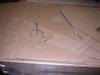
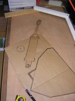
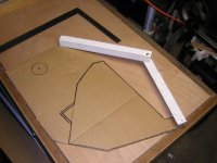
This one shows a template that I made over the winter to work out the best "angle" that I will make the grapple "claws" at. This is before I came up with the cardboard template idea - but same principle - the two pieces of wood are hinged with a 1/4" carriage bolt.
*****************
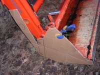
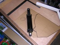
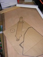
So the next step is to experiment with layouts. I am mulling over the basic design of the toggle / lever system that will convert the linear motion of the hydraulic cylinder into the rotational motion of the grapple jaw opening / closing. As Whiterock pointed out - I'm concerned about mainly two points:
1) force transmission / strain on bucket (due to size of 3" bore cylinder - pressure reduction valve is a viable work-around)
2) location of cylinder to minimize potential damage
I plan on simply driving in finish nails / screws at the hinge points of the lever templates and observe general grapple opening / closing "movements" & clearances - especially with regard to the cylinder / cross tube.
I guess I forgot to note: I made the template with the bucket fully *curled* - so the cross tube - grapple cylinder should only be critical at that time.
************
I thought that might help kick start some other folks' ideas - and it's a lot easier to cut cardboard than steel! (although I'd debate that cutting steel is likely more fun... /forums/images/graemlins/grin.gif )
Hope that helps,
Dan