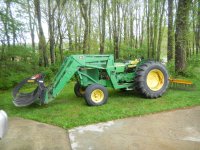
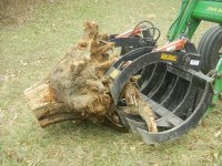
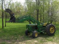
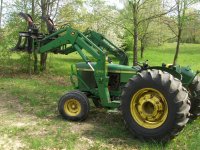
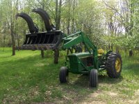
If that works for you then your "numbers" are ok. I need the numbers because I do not know what works and trying to design one that works right away. Make the mistakes on the CAD instead. And hopefully -if I CNC cut the steel- the tabs will be mounted in such a way that I will not have to measure anything.I built a double claw grapple onto a Bobcat LoPro bucket. It works very well and has hundreds of hours of hard use under it's belt.
As I've stated earlier, I'm totally a practical application guy. Your approach is over my comprehension level. So I design by the desired end result. In my case I wanted a large opening. That created the position of my cylinders. I had no idea how much bite force I was going to have until I put it into action. I don't need more force. I'm just a bit disappointed that my design doesn't score any higher.
I struggled a lot with position of the cylinder tabs. Tack welded, cut loose, moved, tack welded, many times to get where I ended up. When fully open and rolled back my claws parallel my FEL frame and curl cylinders so I couldn't open any wider. This "big mouth" design gives me the ability to push loose brush up in a pile, then roll the grapple forward until the claws span most of the pile. Clamp, compress and pick up a huge pile of brush. In the other side I have ability to clamp onto thin material such as plate steel, steel fence posts, or whatever.
Still, just disappointed in my force numbers..... :ashamed:
I cannot see how they fit a 10" cylinder on that size. But I am kind of tired changing the cad. I think I will stick to the 6" for nowThat's what I should have done. Made my frame mount tab taller and more forward, then used a shorter stouter cylinder. Famous last words!!!
Do you know what the stroke length is on that cylinder?
Edit: Never mind, I checked out your link. They say 10". My pea size brain can't figure out how to make that work on mine. My claws and apron must be shorter than theirs. I'll have to take some more measurements of mine.
No obsession on 4" or 6". It is just I cannot fit any longer cylinder on that design. The wicked grapple from EA uses 5" and still have great reviews. And I think my desing is closer to the wicked one. I can try to add the 8". Lets see. If it will give me more opening why not?Not sure why you are still so adamant on wanting to use a 4" or 6" stroke cylinder....when all the mfgs that spend thousands on designing and engineering all use 8" or 10" stroke cylinders.
Why re-invent the wheel.
But you have designing software ability. So whatever works for you.
I'd go no less than 3/8". That's pretty much standard on light and medium grapples.
Its not anything difficult. Google is your friend. Espesially now that the elders:thumbsup: mentioned what to research. I would say the most difficult part is the CAD. But still, I have 11 months CAD experience and I am self taught.I'm following this thread and I really have enjoyed the mathematical approach. I wish one of my high school math teachers had used a real world example approach to show how math can be used after you pass the test... I think it would have really held the interest of many students. I did fine in math, but I remember thinking how I would never use that in real life!
Now I haven't checked the math for accuracy... Nor have I confirmed that the formulas are proper... But I like the approach!
Ok, let the numbers talkJust remember that bigger diameter cylinders are heavier. And every pound you have at the end of the loader is one less pound you can pick up with the grapple. I would use a flow control valve with a smaller diameter cylinder, if the force at the end of the jaws is still enough to get the job done.
") What would you prefer on 6" lenght? 2" with 1510lbs or 2.5" with 2360lbs at the closed position? For an average compact tractor with 30-40hp.
What would you prefer on 6" lenght? 2" with 1510lbs or 2.5" with 2360lbs at the closed position? For an average compact tractor with 30-40hp.