how to build your own custom backhoe subframe

   / how to build your own custom backhoe subframe
  • Thread Starter
#41  
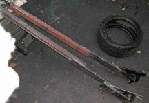
My strategy is to go with a ladder-style subframe with no "rungs", and
an enhanced toplink.

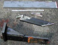
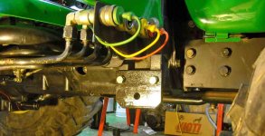
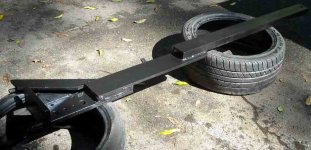
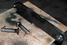
In the first photo, I show the hoe-side 3-pt bracket that comes with
the hoe with the side support cut off. This is very hefty 3.5" x 5/8"
steel. I bought some 1/2" x 4" A36 plate steel (shown) to extend the sides
and to provide the support surface that gets bolted to the modified
ROPS brackets.

Since the width of the ROPS bracket spacing is less than the spacing of
the 3-pt bracket, I will first need to provide a jog of 3/4" on each
frame rail. The pieces of 1/2" x 3/4" steel will be used for this purpose.
An easier approach might be to buy 2 much longer pieces of 1/2 x 4"
plate, and attach them directly to the hoe. This would require putting
2 bends in each rail, but such bends would require rungs to resist
twisting. I have made these bends before, using my press, and they do
look nice. At $5/ft, this plate is not expensive, but I like to reuse
existing materials if it makes sense.

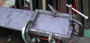
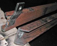
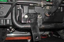
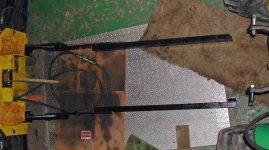
In the 2nd photo, I am ready to weld my small bits of 1/2" steel onto the
plate. To manage heat distortion, I welded the end piece on first, then
worked my way toward the other end of the 2-ft long member. While it
was VERY hot, I welded it to the 3-pt bracket. If not carefull, the 1/2"
plate will bend and require tweaking on a press to straighten it out. (Ask
me how I learned this.) I was able to keep the bend under 1/16" over
the full 2 feet. You can't really do this if you tack-weld it all first.

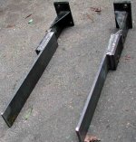
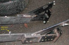
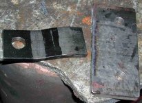
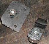
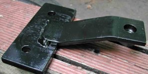
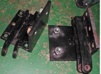
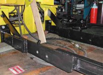
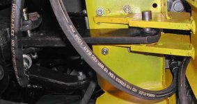
The 3rd/4th photos shows the result. I welded on 2 small alignment guides so
that the hoe/subframe assembly will self-center between the ROPS
brackets during installation. The angular braces are 9/16x2.5" with a
welded on 3/4" bolt to add stiffness, and to make use of the last mounting
hole on the hoe. All of this was bolted to the hoe, then welded. One
came out perfect, and the other took a bit of tweaking to get the bolts
to line up right.
 

Attachments

  • subf_3.jpg
    subf_3.jpg
    61.9 KB · Views: 1,872
  • subf_4.jpg
    subf_4.jpg
    34.9 KB · Views: 1,890
  • subf_5.jpg
    subf_5.jpg
    80.1 KB · Views: 2,209
  • subf_6.jpg
    subf_6.jpg
    77.7 KB · Views: 2,455
   / how to build your own custom backhoe subframe #42  
We do look forward to a day when one of the neighbors does get replaced!
Be careful what you wish for!!!
 
   / how to build your own custom backhoe subframe
  • Thread Starter
#43  
Next, I welded 3x1.5x1/4" channel to the 1/2" plate. I fully boxed
in the connection and provided a big overlap.

At the forward end of one channel, I welded some 9mmx50mm plate
that I bent into a zee shape. The other side has a beefed up hole
to receive a grade 8 3/4" bolt.

To connect to the tractor, I made 2 different brackets to accommodate
the asymmetry of the two sides. I welded the grade 8 nuts to the
brackets to make installation/removal a little easier (only one wrench
needed). Single bolts are plenty strong here because the forces are
much less this far from the rear of the tractor.
 

Attachments

  • subf_7.jpg
    subf_7.jpg
    63.2 KB · Views: 1,645
  • subf_8.jpg
    subf_8.jpg
    59.1 KB · Views: 1,570
  • subf_9.jpg
    subf_9.jpg
    63.5 KB · Views: 1,255
  • subf_10.jpg
    subf_10.jpg
    67.3 KB · Views: 1,373
   / how to build your own custom backhoe subframe
  • Thread Starter
#44  
I could have attached the front of the subframe in several places
forward of the center of the tractor. Initially, I was considering connecting
to the two loader mounting stubs, but I decided to go with the threaded
holes on either side of the bellhousing. I could have also tied into the
engine subframe, but that would have been more work. Primarily, I
wanted to connect forward of the large hole in the bottom of the
bellhousing, which is a weak point in the tractor's structure.

Since the two sides are different, the brackets are different. The main
hydraulic inlet to the pump was in the way on the left.

These mounting points allow the subframe rails to hang barely below the
lowest hanging part of the tractor, so little ground clearance is lost. This
also provides protection for the vulnerable hydraulic underpinnings.
 

Attachments

  • subf_13.jpg
    subf_13.jpg
    59 KB · Views: 1,905
  • subf_12.jpg
    subf_12.jpg
    62.5 KB · Views: 1,786
  • subf_11.jpg
    subf_11.jpg
    42.8 KB · Views: 1,202
   / how to build your own custom backhoe subframe
  • Thread Starter
#45  
Next I completed the ROPS brackets by drilling holes and welding on
some extra-long grade 8 nuts. Like the forward brackets, secured
nuts will make tightening and removal easier. I try to torque these
at at least 100 ft-lbs. After a shot of black paint, I can permanently
install these.

The second photo shows one of the frame rails completed, except for
the rear mounting holes. I will now need to dry fit both rails (photo 3) and
attach the hoe/subframe assembly to the tractor at the forward
brackets. I back the tractor over the subframe and use the hydraulics
to raise the hoe (pivoting on the forward bolts) until it lifts the tractor
a bit. That means the axle housings are resting on the subframe rails.
Now I scribe inside the existing holes in the ROPS brackets to give
me a precise location for the four frame rail holes.

Then I take it all apart again to drill my holes on the drill press (last photo).
In this photo you can see my wooden mockup of my toplink, which I
will make next.
 

Attachments

  • subf_16.jpg
    subf_16.jpg
    65 KB · Views: 1,355
  • subf_14.jpg
    subf_14.jpg
    56.5 KB · Views: 1,383
  • subf_15.jpg
    subf_15.jpg
    52.8 KB · Views: 1,458
  • subf_17.jpg
    subf_17.jpg
    69.9 KB · Views: 2,060
   / how to build your own custom backhoe subframe
  • Thread Starter
#46  
Now I need to make an "enhanced" toplink to support the upper part of
the backhoe structure. I used a toplink from the 3-pt hitch that comes
with these hoes, cut down to only about a foot long. I used the wooden
board above to make a mockup first so my cut will be close to what I need.
The tractor-side bushing was tacked while in place, then welded up
off the tractor.

The first photo shows the view from below the seat. You can see where
the completed toplink uses the bottom of 3 holes in the tractor's toplink
support. To get the holes to line up, I had to grind a depression in the
top of the toplink (2nd photo) to clear the seat mounting platform.

Finally, I made pins. I used 13/16" round stock, rather than standard
3/4" cat 1 pins because the cat 1 connections are too sloppy. They are
designed that way. A 13/16" pin fits right in with no modifications to the
bushing or the pin holes....there is probably just a few thousanths
clearance. Perfect.

Next comes the seat.
 

Attachments

  • toplink_1.jpg
    toplink_1.jpg
    45.8 KB · Views: 1,791
  • toplink_2.jpg
    toplink_2.jpg
    56 KB · Views: 1,550
Last edited:
   / how to build your own custom backhoe subframe #47  
dfkrug: Just dropping by to say thank you very much for this thread, its great!
It gives me a lot of good advice/tips on how to fabricate my own sub frame for my soon to be delivered backhoe.

The backhoe i am waiting for is a side-shift type so it narrows it down to just a few sub frame designs. Its leaning towards the ladder type, a extension from the FEL sub frame which goes from the front to the rear axle.

Here is a picture on the mounting points i have to play with on the back of the backhoe, as you can see there is not much room. This is the 6' model mine will be the 7,2' model as in the other picture of some guys setup. This backhoe has a break out force of 4850 lbs and weights 970 lbs. With such power it feels that without a sub-frame there is a big risk to break the back of the tractor.

How would you have done it?

Cheers!
 

Attachments

  • 2.jpg
    2.jpg
    337.1 KB · Views: 1,994
  • 130610.jpg
    130610.jpg
    312.1 KB · Views: 2,085
Last edited:
   / how to build your own custom backhoe subframe
  • Thread Starter
#48  
Here is a picture on the mounting points i have to play with on the back of the backhoe, as you can see there is not much room.

Interesting hoe....Italian?

The hoe side is far easier than the tractor side, in my experience. Looks
like a decent sized Massey-Ferg tractor. Can you get a subframe around
the rear axle housings? How does the FEL subframe attach to the rear?
It is generally good news that the FEL subframe goes all the way back
there. Also good news about the AG tires, since you have some width
adjustability for clearance.

You can also use those 3-pt hitch clevises on the hoe to weld on some
brackets.
 
   / how to build your own custom backhoe subframe #49  
dfkrug: Just dropping by to say thank you very much for this thread, its great!
It gives me a lot of good advice/tips on how to fabricate my own sub frame for my soon to be delivered backhoe.

The backhoe i am waiting for is a side-shift type so it narrows it down to just a few sub frame designs. Its leaning towards the ladder type, a extension from the FEL sub frame which goes from the front to the rear axle.

Here is a picture on the mounting points i have to play with on the back of the backhoe, as you can see there is not much room. This is the 6' model mine will be the 7,2' model as in the other picture of some guys setup. This backhoe has a break out force of 4850 lbs and weights 970 lbs. With such power it feels that without a sub-frame there is a big risk to break the back of the tractor.

How would you have done it?

Cheers!

That is a very interesting design. I have never seen one like it but it would certainly be useful...similar to the side shift boom on a lot of mini ex's that let you dig parallel to a wall or foundation. Is the shift hydraulic? It doesn't appear so from the pictures but surely it's not manual and there doesn't appear to be a rack or screw either. How does it work?
 
   / how to build your own custom backhoe subframe #50  
Interesting hoe....Italian?.......
.

Sorry for late reply. I will post some picture of the rear axel/ FEL attachment point soon. And you are correct, its a Italian Backhoe.

That is a very interesting design. I have never seen one like it but it would certainly be useful...similar to the side shift boom on a lot of mini ex's that let you dig parallel to a wall or foundation. Is the shift hydraulic? It doesn't appear so from the pictures but surely it's not manual and there doesn't appear to be a rack or screw either. How does it work?

You move it from side to side with the boom and dipper, and the locking and unlocking is hydraulic.

Here a tube video on a other Italian brand with side shift were you can see how its work. YouTube - Tifermec Heckbagger Mobilbagger

In Europe there are very few fixed pivot backhoes, all is side shift. You win in versatility but loose some in stability. The side shift frame on the blue 7' model is 150 cm wide ( 5 feet).
 
Last edited:

Tractor & Equipment Auctions

2007 John Deere 320 (A47164)
2007 John Deere...
2022 Club Car Tempo Golf Cart (A48082)
2022 Club Car...
1998 Chrysler Sebring JXi Convertible (A48082)
1998 Chrysler...
FLOWTRONEX SYRINGE FAN (A50460)
FLOWTRONEX SYRINGE...
Linde H25T 5,000lbs Propane Forklift (A49346)
Linde H25T...
UNUSED Steel Diamond Plate (A50860)
UNUSED Steel...
 
Top